 LV5
LV5
Me
#Tech tips Share your welding progress, a question or a finished build…
Public Post
LV5
So with this thing, if I just power it from a high-power charger, can it convert current and voltage to work as a universal charger?
 Ep. 45 | An adjustable power supply with high-end features at rock-bottom cost? Building a portable, precise, digitally controlled adjustable supply from simple materials at the lowest cost — the result is a surpriseProjectsRural Abiao
 LV5
LV5
Abiao hand-builds a portable rechargeable mini drill press (11 minutes, open-sourced on MakerWorld): 795 motor 12–24V, 20/60-tooth pulleys, tapered / linear bearings, shafts, 3D-printed parts; 6 × 18650 2600mAh 10C in 6S + 35A balancing BMS + IP2369 45W 2–6S charge/discharge module + meter + rocker switch, one balance lead per series group, first power-up needs 2–3V extra to activate, 21V output; v1 had the tapered bearings fitted the wrong way and melted from friction, remodelled and perfect: square steel cut like tofu, threaded rod drilled most of the way through
He had a set of pulleys but no mini drill press, so built a portable rechargeable desktop drill press with no cord; drills square steel like cutting butter and even large threaded rod. Materials list (with prices): 795 motor 12–24V ¥28.9, drill chuck + 5mm adapter ¥15.28, 20/60-tooth pulleys ¥12.1, two tapered roller bearings (10mm bore) ¥10, linear bearing ¥5.5, flanged linear bearing ¥15.2, 10mm shaft 40cm (¥17.5/m), 5mm shaft 10cm (¥39.9/10), M6×90 hex socket screws ¥3.73/5 sets, small 5×10 bearings ¥17/10, springs ¥4.3/10; electronics: 6 × 18650 2600mAh 10C (¥343 per 100), 6S 35A balancing BMS ¥23.74, DC 7–100V charge meter ¥10.9, IP2369 PD 45W 2–6S charge/discharge module ¥21.3, 6mm rocker switch ¥1.9; if you don't want Li-ion, skip the cells and BMS and run direct DC; if you don't have a spot welder and other professional tools, better not build a Li-ion pack. Battery: main positive and negative brought out on nickel strip to the BMS; many people struggle with balance leads, just remember: from negative to positive, one per series group, sampling each group's voltage; fit the balancing BMS and spot-weld the negative, plug in the balance leads; some BMS boards need an input 2–3V higher than the pack for a second or two on first power-up to activate; measuring around 21V output means it's active. Mechanical parts modelled to size, free and open-source on MakerWorld, PLA printing takes four plates and a dozen-odd hours, ¥20-odd in filament. Assembly: cells into the box recess, fit the charge meter, main positive reserved as a lead, charging module glued in at the Type-C cutout; meter negative, charger negative and main output negative all go to the BMS negative output; BMS charge input lead to the charging module negative, the other to the module positive, flick the module's little switch and the light comes on, working normally, Type-C both charges and can discharge to a phone; the pack positive's other lead goes to the switch's centre pin (input); output load lead, meter positive and sense lead twisted together onto the switch output; switch into its reserved hole; power on, meter lights up, close the lid; tap the shaft into its round hole. Head: small bearings top and bottom, tapered bearing (10mm bore printed adapter down to 5, tight space makes it a struggle to fit, a design failure), drill-bit adapter, flanged linear bearing with 4 screws, the other linear bearing, chuck, motor bracket with 4 screws, motor, small pulley grub screw, belt (better to fit the belt before the pulley); turntable base with two screws, loosen/tighten to adjust table height; the bottom clamp's third set of hex screws adjusts bit angle; springs on the two vertical rods; the handle's pivoting link copies an old hand-pump well, copper wire through the outer hole to stop it slipping off; power leads to the motor, dust cover. Test drill: after one hole it wobbles and vibrates badly, the shaft isn't vertical, the head model has a serious problem; taking it apart shows the plastic already fused and scorched; while drilling the bit pushes upward, rubbing the plastic until it heats and melts; remodel so the tapered bearings go in from the outside, one top and one bottom, stopping upward push and downward drop, the bearing inner race spins with the bit without rubbing; found that the small bearing's 10mm OD works as a reducer for the 5mm shaft; nearly two hours to reprint, fitting difficulty and friction heat perfectly solved; square steel like tofu, threaded rod not quite all the way through but close, good enough for a desktop mini drill press. Comments: made one too (4); don't cost it at 10cm, nobody sells 10cm; how much do you spend a month on inventions; add a fixture to turn beads; make it waterproof to cut bottles; main column too thin and too many plastic parts, poor rigidity, fine for fun; the rear column needs a really thick tube; can you make a mini table saw (tutorial coming).
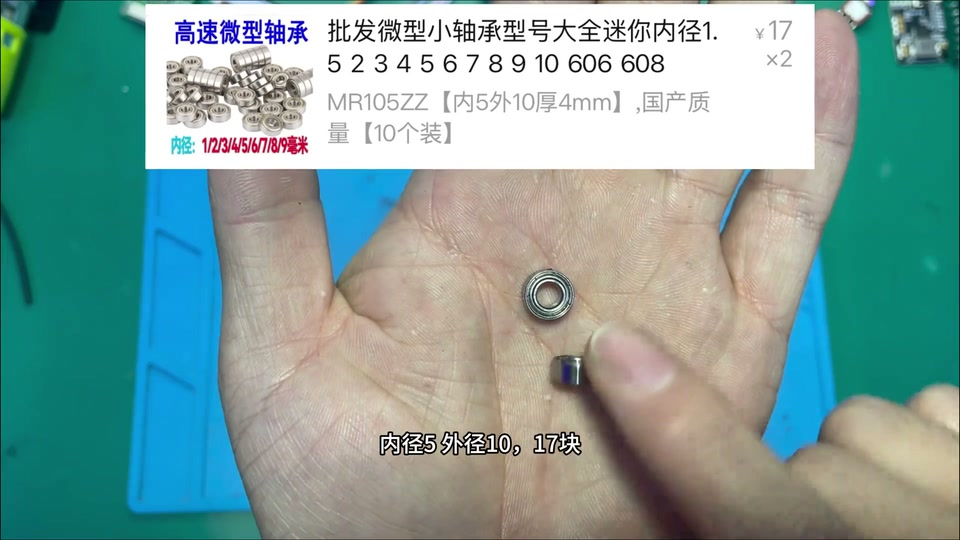

 Ep. 66 | How to hand-build a portable desktop mini drill press? Build a DIY maker's own desktop drill press that can even drill into rebarProjectsRural Abiao
Who to followRefresh


 LV5
LV5
Abiao from the village DIYs a portable rechargeable belt grinder for knives (903 likes): belt-grinder head kit ¥44 + 795 motor ¥28.9, a heat-shrunk bushing to fit the shaft, 3D-modeled and printed base / housing / motor bracket (promised open source); battery 9 × 18650 2000mAh 5C (¥3 each) in 3S3P 12.6V 6000mAh, nickel tabs spot-welded in a “box” pattern for the parallel / series joins so the balance board works, fish paper on, 3S 60A separate-port balance BMS ¥6.1, Type-C charging module ¥11.8, battery meter ¥10.9, latching lit button ¥6.9, 6-pin rocker switch for forward / reverse, ¥15.3 buck-boost stepped up to 24V to make the 795 more brutal; total cost ¥100-something; sharpens well; comments: isn’t the bottom of a bowl good enough, add a rest to fix the angle, does dry grinding anneal the edge (no)
The kitchen knife is blunt; experts use a whetstone, I’m a novice, so build a portable rechargeable belt grinder: forward / reverse adjustable, charge display, a neat power switch, stepless like a gas pedal; kitchen knives and machetes come up sharp with a quick pass, belts are swappable, one minute and it cuts vegetables like tofu; cost ¥100-something. Core parts: belt-grinder head kit ¥44 (comes with 5 belts, drive wheel / idler); 795 motor ¥28.9 (with mount and dust cover, 200W). Assembly problems: the motor shaft is smaller than the drive-wheel bore, so buy 5mm ID / 8mm OD bushings (¥19.5 for 5), heat the drive wheel so it expands and drop the bushing in, then lock the grub screw to clamp the motor shaft; the frame holes don’t line up with the motor holes and can’t be drilled (the original design wasn’t for a 775/795), so he models a base and housing (with battery bay and slots for the electronics) plus a motor bracket, 3D prints them, and will release the models free and open source; two screws hold the bracket to the motor, the other side to the steel frame, drive wheel fitted; changing a belt means removing the idler; a quick power-up to fine-tune the idler until it runs smooth. Battery: for portability, 18650 2000mAh 5C-discharge at ¥3 each, 9 cells for 12V (3S3P, 12.6V 6000mAh); battery meter DC7-100V ¥10.9; forward / reverse via a KCD1 6-pin 3-position rocker switch, ¥13 for 10; Type-C 3S charge-management module ¥11.8. Spot-weld the nickel tabs on; note the parallel / series joins are welded in a “box” pattern so the balance BMS actually works, otherwise it only balances one group; wrap in fish paper for insulation and heat isolation; fit the 3S 60A 12.6V balance BMS (¥6.1) — separate-port, so both input and output leads must be connected; pack goes into the printed box, input side to the Type-C charging module, plug in and it charges normally. Fit the lit metal latching button ¥6.9: switch input to the pack’s output positive; button negative and meter negative twisted into one lead; meter positive, sense lead, switch output and switch positive twisted into one lead; the negative lead to the pack’s output negative; into the input of the adjustable buck-boost module ¥15.3, then the master switch; the light comes on, so the wiring is OK. Forward / reverse rocker switch: the middle pins are the power input, and whichever of top or bottom is used as output needs two jumpers crossed to the other side’s pins — the principle is simply swapping positive and negative; switch input from the buck-boost output; the buck-boost raises 12V to 24V so the 795 is more brutal and spins faster; not building 24V directly because 12V is smaller, portable use doesn’t need long runtime, and 12V parts are in stock. Output leads out of the box to the motor; lid on; the frame bottom is screwed to a bracket and strong glue fixes the frame to the box base; motor positive and negative connected; job done; test grind works really well and fast, usable for DIY too. 102 comments: this is the way, no argument (7); is a 12V motor enough? why forward / reverse for sharpening? sourcing (2) → every part has detailed sourcing info in the video; where to buy components / is LCSC reliable (2); add a rest to fix the angle (1); an angle grinder takes seconds → too aggressive, the edge quenches; does dry grinding anneal it → no; isn’t a bowl bottom good enough (many); wasn’t this on your livestream → yes; posting at 4 a.m. → afraid of copycats; which 3D printer; the kit is only ¥40-something, don’t rip people off; help fix two streetlight lithium packs.


 Build your own portable knife-sharpening gadget that every home needs? Kitchen knife gone blunt? Build a portable belt grinder on the cheap and never worry about a dull knife againProjectsRural Abiao
LV5
Build your own portable knife-sharpening gadget that every home needs? Kitchen knife gone blunt? Build a portable belt grinder on the cheap and never worry about a dull knife againProjectsRural Abiao
LV5
A Biao’s ‘New Year atmosphere machine’ (17 minutes, 4038 likes, MakerWorld / code open-source): scrap steel pipe and rebar welded into an angle-adjustable five-shot firecracker rack with rubber-band auto-feed; voice module (ASR-PRO) → ESP8266 transmitter over WiFi → ESP8266 receiver (700-line config web page) → relay → 24V high-voltage arc igniter; the 24V pack is 6 old salvaged 1500mAh 18650s spot-welded in series (24.63V), the 6S 35A balance BMS needs 26V to activate, CC/CV buck-boost charging at 25.2V, XL4005 stepping down to 5V for the MCU; the transmitter runs on an 18650 + 5V common-port module; live test: ‘fire!’ and it fires in sequence
Opens with ‘Second Battalion Commander, your Italian cannon’. The romance the New Year deserves: walkie-talkie in hand, set off firecrackers remotely by voice, load 5 at a time for burst or single shots; materials are scrap steel pipe and rebar plus a few dozen yuan of electronics; the principle is a WiFi transmitter and receiver controlling ignition. Mechanics: cut pipe and weld a rack, a pivoting joint at the bottom to adjust the angle, a tail so it stands stable; the front support uses old rebar and galvanised pipe, also adjustable; firecracker clip: slot the pipe for the clip bracket, weld a slide on the short end on the other side, weld as many pipes onto the base as shots you want (5), weld nuts at the head and the slide’s tail, cut a fuse groove in the pipe; the clip rides the slide, a rubber band through the screw hole anchors to the base, and after ignition it springs to the next one for automatic feed. Electronics (with shopping screenshots): one 2000mAh 18650 (¥3) powers the walkie-talkie (transmitter) with a 5V charge/discharge module (¥2.85); 6 old salvaged 1500mAh cells make the 24V pack with a 24V 6S balance BMS (NMC 6S common-port 35A with balancing, ¥25.74); a CC/CV adjustable buck-boost module (¥15.3) charges the pack, 5–30V wide input; an XL4005 adjustable buck module (¥5.5) takes 24V → 5V for the MCU; a USB port powers the ESP8266; 2 × ESP8266 (¥13.94), one transmit, one receive; ASR-PRO voice-recognition dev board (¥26.2) + small speaker; 5V relay module (¥2.9) switches the ignition; 24V high-voltage ignition kit (high-frequency transformer, two pins produce an arc). Programming: the voice module uses the vendor’s Chinese block-based tool, wake word ‘Second Battalion Commander’, commands ‘bring up my Italian cannon / fire / open fire / launch / stop / continuous fire / stop continuous fire’, sent over serial to the ESP8266, with synthesised voice generated in the model and flashed; the transmitter ESP8266 in VSCode PlatformIO: opens a hotspot + TCP server, relays the voice serial data, reconnects on drop, 300-odd lines; the receiver connects to the transmitter and handles ignition / auto cut-off / continuous fire, with its own hotspot serving a phone web page for settings (cut-off time etc.), 700-odd lines; flash and test via serial log. 3D-modelled boxes (ignition head, receiver box, transmitter box), open-source on MakerWorld for printing. Assembly: remove the ignition head’s HV leads, pass them through the box and re-solder, lengthen the power lead; the 24V pack is 6 cells in series, 25.2V full, 24.63V on the multimeter after spot welding, wrapped in fish paper, main + and − nickel tabs spot-welded on; balance leads run from the main positive, one per group in order; the balance BMS only takes the negative input and negative output, the positive bypasses the board and goes straight out; plug in the balance leads; the BMS is inactive by default and needs a moment of 26V+ to activate; voltage tests fine, boxed up, snug fit; the buck-boost output set to 25.2V and connected to a parallel pair of leads on the pack; the 24V output feeds the buck module set to 5V; forgot a switch, so cut the lead, extended it and added one; 5V leads to the USB socket; the relay also needs 5V, taken from the 5V buck; the buck-boost output also feeds two 24V leads, positive through the relay to the ignition head; relay 5V + IN signal + 24V in/out extended to the ignition pack, controlled by the ESP8266 high/low level; fit the ESP8266, Type-C power, aviation-connector socket as the charge port; power-up test — charge LED on, the switch wiring doesn’t smoke, manually triggering the relay gives a normal arc, receiver done. Transmitter: the voice module’s two serial wires go to the ESP8266 serial with RX/TX crossed; 18650 + 5V common-port module, nickel tabs spot-welded onto the cell to make soldering easier, then + and − leads soldered on and into the module input, Type-C charging with green flashing for charge and blue for discharge; two Type-C leads with + and − paralleled into one input, plus a switch (one end to 5V +, negative straight through, switch output to the Type-C +); fit the ESP8266, speaker on the lid, voice module, Type-C common-port module; the two Type-C leads feed the voice module and the ESP8266; power-on test, ‘fire!’ OK; lid on, a decorative ‘soul antenna’; phone into the config page to set auto cut-off time / continuous fire; the ignition head is fixed to the rack with an acrylic sheet for insulation, ignition pins glued so the arc lights the fuse; outdoor test, ‘fire!’, fires in sequence, works really well. 257 comments: does this count as manufacturing a firearm (an entertainment toy, not a weapon); I’ve only programmed 8266 with Arduino, can I learn this (absolutely); how to program it (follow the video); a rotary-drum launcher would be perfect (sold online); is it open-source; the pipe has no rifling; won’t the police have a word; are you selling, how much; fireworks are banned.
 I built a ‘New Year atmosphere machine’? If your village had a voice-controlled remote firecracker toy like this, would you stay home a few more days over the New YearProjectsRural Abiao
LV5
I built a ‘New Year atmosphere machine’? If your village had a voice-controlled remote firecracker toy like this, would you stay home a few more days over the New YearProjectsRural Abiao
LV5
Abiao from the village (an embedded programmer) goes home and fixes appliances for free, vlog (2644 likes): a rice cooker with a loose connection, a hair dryer with burnt switch contacts repaired plus a varistor suggested, a cordless drill’s 5S battery bay re-celled (1500 → 2000mAh with 3C certification, internal resistance 17mΩ and matched, fish paper on, series nickel strips / main + and − / balance leads spot-welded, BMS refitted, red charge light, drill pulls hard), two membrane keyboards merged into one, a hair dryer plug replaced; comments: five cells out of his own pocket, he lost his shirt
An embedded automation programmer goes home and fixes appliances for the village elderly for free. 1) Rice cooker: the light flashing on the repair socket means a loose connection, just push it in firmly; boil water to test the response, water temperature rising from 35°C, heating ring at 100-plus, one done. 2) Hair dryer: no response from the switch, so the switch is suspect; two screws out, it has been opened before and the switch tied with string; multimeter on continuity, the switch pressed shows no continuity; the switch clip is broken, inside is a copper leaf + latch + spring, the two contacts on the copper leaf are burnt, and a diode is wired in for the speed change; no such switch on hand, so the burnt parts of the contacts are cleaned and it goes back, fixed with strong glue instead of string; gear one and two latch fine; the original soldering was sloppy — joints must be solid or they arc, and an arc at the grip is dangerous; suggest a varistor in series across the switch input / output; powered up, back to full health. 3) Cordless drill battery bay won’t charge: odd screws, swap the bit; barely charges and the gauge drops on one press, most likely the cells need replacing; 5S, 21V at full charge; when removing the BMS mind the 4 balance leads; clean off the old nickel, keep the holder; originally 1500mAh each, replaced with 5 new 2000mAh cells with 3C certification; measure every cell’s internal resistance before fitting, this batch all around 17mΩ, fine for a Li-ion drill’s power needs; the original had no fish paper but a ring is best, the 18650 shorts most easily right at that ring; in series order, spot-weld the series nickel strips first, then the main + and − strips, last the balance leads; refit the BMS, tin with the iron and solder the balance-lead nickel strips to the board, connect the main + and − last; check for cold joints; fish paper back on, into the battery bay, screws in; the red charge light is normal, the drill pulls hard. 4) Two membrane keyboards merged into one: swap the cable, note the wire order and numbers, the membrane contacts must line up with the board and be pressed with the clamp bar, cable into its slot, add heat-shrink. 5) Hair dryer plug with one long and one short pin: fit a rice-cooker cord, high power so tin the joints to avoid heating, wrap in tape and heat-shrink. Sign-off: night view of the mountain hollow, ‘maybe I can’t make my hometown rich, but I can contribute a little with what I’ve learned’. 260 comments: five cells out of your own pocket, don’t do this kind of job again (3) → creator: lost my shirt; suggest more close-ups (screws, soldering, multimeter readings) → noted; hold the iron by the grip (proper practice); serving the people, down to earth; that workbench is my dream → I’ll make one.
 A programmer goes home and fixes appliances for the old folks? I’m an embedded automation full-stack developer, and I repair appliances for the elderly in my hometownProjectsRural Abiao
 LV5
LV5
Lefeng’s 20S Jiashikai 32140 (6045) big pack, ‘don’t get blown up’ chapter: mark the series positions after the fish paper; punch the 0.2×50 copper strip, thread the wire, solder, then seal with glue; the 1–20 link order and its flip-side match; P60F at gear 587 (of 999), copper strip under, nickel strip on top; repeated warnings that a wrong link on the other face is a short that blows you up — have respect; continuous welding makes the pen hot, 11 pieces done then off to deliver orders
A detail lesson for beginners. After the fish paper is on, always write the series-group number at each position, so the connection order lines up. Mark and cut the 0.2 copper strip (it’s quite heavy), punch holes in it: when soldering, twist the wire into the hole first, then add just a touch of solder, then seal with a dab of glue. Connection logic: on the first face join 1 to 2, 3 to 4, 5 to 6… up to 10; on the underside the matching positions are 4–5, 5–6, 6–7, 7–8, 8–9, 9–10; group 10 gets a long strip across to the far side; flip over and do 11–20 the same way. Someone said laying that piece on top is dangerous — it isn’t dangerous right now because the underside isn’t connected yet; once the underside is connected, laying it like that will spark. Join it cluster by cluster: finish this side, flip, then join the matching face — never connect the wrong ones, a wrong connection is a short that blows you up, bro. Settings: AWithZ P60F, gear 587, settled after a lot of trial runs; it tests your technique: copper strip underneath, nickel strip stacked on top, then weld; trim the surplus corners. When you flip, the two cells joined underneath on this side must not be joined again on top, or it shorts; group 20 is effectively the main positive; laying four like this is fine, laying six like that shorts; you must have respect for it — getting blown up is truly terrifying, no joke. Partway through, lift the strip now and then to check the welds are solid — the gear has been tuned countless times but still check. Continuous welding makes the pen hot; 4 pieces on that side, 8 on this side, then 3 more — 11 pieces — off to the evening rush to deliver orders, more when there’s time. Comments: is it Jiashikai 32140 (Jiashikai); copper strip 0.2×40? (0.2×50); can the UF20B stack 0.2 copper (no; with a nickel base it can stack 0.1–0.15 copper); building a 6045? (yes); which gear? (P60F has 999 gears, I use around 600); everyone says AWithZ is junk, is it true; when will you upgrade to laser welding.


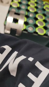 This lesson is all detail for beginners — the chapter of the hand-built Li-ion course that keeps you from getting blown up, bro! Old hands, now it’s your turn to roast meProjectsCrazyFun
Related productsAll ›
 LV2
LV2
Maker Zhou Xiansheng’s step-by-step universal magnetic base guide (3325 likes): cells + box + charge/protection board + DC module + magnetic socket; a spare plastic box holds three 18650s, welder puts them in parallel ‘just rattle off the welds’, cut a hole to bring out the Type-C, solder charge board output → DC module input, protection board battery port and DC output, verify charging, glue it in, mark and drill the lid centred, push in the magnetic socket and solder + / −; pair it with whatever lamp you like
Lots of folks wanted the universal magnetic base guide, so this episode does it. Main materials: cells, a box, a charge/protection board, a DC module, a magnetic socket; the box can be wood, metal or even a brick, and the number of cells follows the box size; he picked a spare plastic box (comment: a floss box) that fits exactly three cells (comment: Samsung cells). First use the welder to put the cells in parallel — nothing fancy, just rattle off the welds, check they’re lined up and done; three fit in perfectly. Cut a hole to bring out the charge/protection board’s Type-C port; solder the charge board output leads, the DC module input leads, the protection board battery port and the DC module output leads; finally connect the cells and verify charging works; put the cells, protection board and DC module in the box and glue them down; mark and drill the lid as centred as possible for looks; push the magnetic socket into the hole and solder + and −; done, test the charging once more, perfect; how great is this universal magnetic base — pair it with whatever you want, use whichever lamp you want. 157 comments: why does the cheap 18650 charge/discharge module’s LED stay on (4); what does the DC module output; why is the 4056 double-layered / two input boards (creator: good eyes); Samsung cells are extravagant (a friend gave them); a 3D-printed base would be even better.
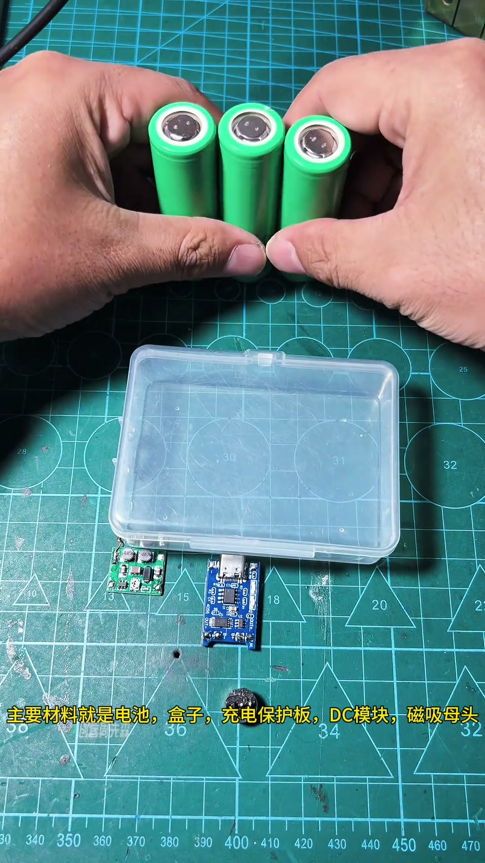

 Universal magnetic base build guide — the step-by-step build guide for the universal magnetic base is hereProjectsMaker Zhou
LV5
Universal magnetic base build guide — the step-by-step build guide for the universal magnetic base is hereProjectsMaker Zhou
LV5
Lefeng admits he hasn’t figured the U3 out: the Jiashikai negative is steel, so he tests on a stainless-steel knife — 0.1 nickel strip only needs gear 1.5–1.8 (anything around 1.x is fine), 0.15 nickel strip at gear 2.5 blackens and throws sparks, not good, still not dialed in; cells are on the way and he’ll keep experimenting; comments: ordered from the storefront and it won’t power on, microwave-transformer welder also failed, once you get into it you’ll want a capacitor unit
The comments say I can’t even figure out the AWithZ spot welder; honestly, I haven’t, I’ve tried lots of settings. Because the Jiashikai negative is steel, I test on a stainless-steel knife: for 0.1 nickel strip on this cell the gear only needs to be 1-point-something, 1.5 is enough, and there won’t be a problem; how many gears 0.15 nickel strip needs I don’t know, bumped to 2.5 to try: too high a gear blackens it, it’s already throwing sparks, the result isn’t great, probably still not dialed in; the cells are bought and on the way, I’ll keep experimenting with this AWithZ spot welder. Title: 9.9 gears, 0.1 only needs gear 1.5–1.8; “I haven’t figured it out and you’re still buying it after me, unbelievable”. 207 comments: ordered from your storefront, arrived today and won’t power on (check whether it has charge; if it doesn’t work, return it right away); my microwave-transformer welder failed too (you’re going down the road I went down; the money for a hand-build buys one of these); a Zhongwei Zhixing 30s can’t weld 0.1 nickel-plated stacked on 0.1 copper to a Jiashikai negative (0.1 copper needs a ¥400–500 class machine); fine for beginners to play with but later you’ll definitely want a capacitor unit (yep); get a UF20B; how about the Xiaoqiang.
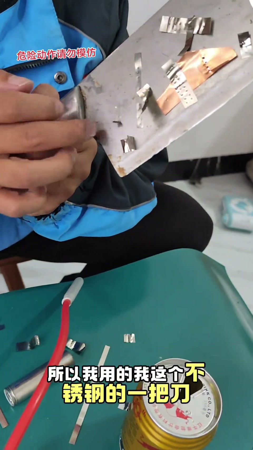

 Honestly, I haven’t figured this spot welder out — 9.9 gears, and 0.1 nickel strip only needs gear 1.5 to 1.8! I haven’t figured it out and you’re still buying it after me, unbelievableProjectsCrazyFun
LV5
Honestly, I haven’t figured this spot welder out — 9.9 gears, and 0.1 nickel strip only needs gear 1.5 to 1.8! I haven’t figured it out and you’re still buying it after me, unbelievableProjectsCrazyFun
LV5
Lefeng heads home for National Day with gear (multimeter, AWithZ U3, cells bought online, iron, nickel strip) and opens a 10,000mAh power bank at home: 3 of the 5 cells are fakes with no voltage — ‘fake Li-ion cells have a long history’; removes them, keeps 2 good cells, adds new ones in parallel; tape for insulation; U3 set to gear 5 (screen shows 3.2) welding 0.15 nickel-plated stacked with 0.1; a nickel-strip short blisters his hand; assembled, charges a phone, shell glued
Opens with a burnt hand by accident; looking at the delivery-order numbers these days, no more grind — home for National Day, with gear: multimeter, AWithZ spot welder, the ‘fake’ cells bought online (a joke), a small soldering iron, solder wire, the bought cells, nickel strip; also found a power bank at home (3.7V 10,000mAh) and opened it — of the five cells, three are different and not connected together, two are connected; turns out those three are fake Li-ion cells, ‘fake Li-ion cells have such a long history’; measured no voltage on the three, removed them with the iron; red +, black −; the good ones and the new cells go in parallel and back in; nickel-strip leftovers, only this tape at home for insulation. At the key moment out comes the AWithZ spot welder, because it’s small and light — bringing the big welder home would be too heavy and a hassle; screen shows gear 3.2, ‘set it to about 5’; 0.15 nickel-plated steel strip is a lot thicker, a layer of 0.1 stacked on top; welded, + and − soldered with the iron; (BGM) hand straight-up burnt with a blister; power bank assembled, charge the phone as a test before fitting the shell; shell glued on. Comments: the pulse is too long, it’s arcing (so that’s it, thanks); get an internal-resistance tester and match cells, it’ll last longer (coming later); a nickel-strip short did it (stay safe); can it still be saved (isn’t that what you’re doing); put those two in as well (they’ve been around too long, no good).
 Once you’ve mastered hand-building Li-ion packs you’ll never buy a power bank again — all the old power banks at home can be re-celled! HahaProjectsCrazyFun
LV5
Once you’ve mastered hand-building Li-ion packs you’ll never buy a power bank again — all the old power banks at home can be re-celled! HahaProjectsCrazyFun
LV5
Lefeng gives up on hand-building a welder and buys the Douyin no. 1 seller, the AWithZ U3 Pro edition (11000mAh): unboxing (thick welding pen, nickel strip, USB output, manual key), auto mode fires the moment it touches and blows through 0.1 strip, ‘a bit fierce’, switches to manual; two welds on 0.05 copper can’t be pulled apart, it tears and still leaves the welds; 99 gears (9 coarse, with fine steps), interval left untouched; doubles as a power bank, ‘spend your power-bank money on this, it’s very good’; 550 comments backing capacitor welders / Xiaoqiang / transformer welders
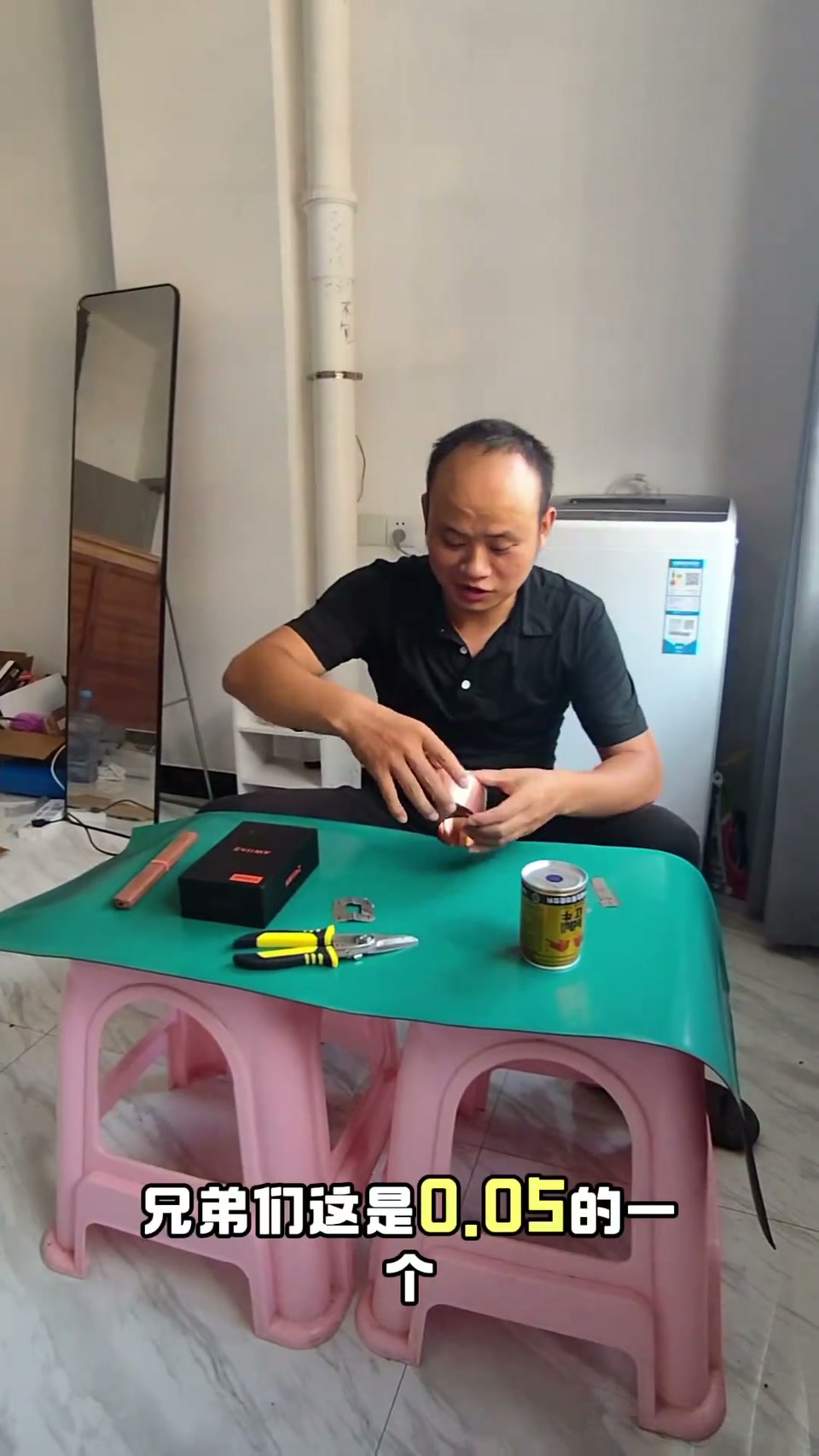
The old welder couldn’t stack copper and hand-building was a detour, so he got the Douyin no. 1 seller, the AWithZ U3 Pro (picked up at the Cainiao station, 11000mAh). Unboxing: main unit box, the welding pen looks pretty thick, nickel strip too (check the thickness), the small holes on the cable are for the switch; long-press to power on, the screen shows interval / preheat (milliseconds) and mode auto; the top port is USB output for charging a phone, there is a separate charging port; the M key is the manual weld key (trigger in manual mode). First try in auto mode, set it down and it fired without pressing the switch, ‘gave me a fright, a bit fierce’, went straight through the 0.1 (steel strip), probably the gear wasn’t set right; switched to manual, where it only welds when you press the switch; that last weld was very solid, steel strip 0.05. Gears: 9 coarse gears each with fine steps, 99 gears in all; interval not adjusted. Two light welds of 0.05 copper on a 26650: can’t pull it apart, it already tears, and pulled off it still leaves two welds behind that won’t come off, welded very securely, much better than the old welder, handy and compact and doubles as a power bank; no cells on hand so the test ends there; spending your power-bank money on this is a good deal. 550 comments: the Xiaoqiang capacitor welder stacks 0.15 copper and is more reliable (creator: buy buy buy); why buy another battery welder, still on the detour, capacitor is the way to go (getting ready for a 45A battery next time); don’t mess with NMC, it explodes; for value it’s still Xiaoqiang; AWithZ really is good, well built; microwave-transformer welder was no good so also got an AWithZ 539; going to buy a Glitter 811H; a dual-900W transformer welder is far stronger, battery welders max out at 0.4 and the internal battery fades; with that money buy a Xiaoqiang.

 Do you really have to hand-build a spot welder to hand-build Li-ion packs? Don’t take my detour — see what you make of this oneProjectsCrazyFun
LV5
Do you really have to hand-build a spot welder to hand-build Li-ion packs? Don’t take my detour — see what you make of this oneProjectsCrazyFun
LV5
Hand-built portable digitally controlled adjustable supply: 3S4P 18650 + 3S40A BMS, boosted to 36V then through a digital buck module with coulomb counter, 0–33V adjustable with adjustable current
The creator wanted an adjustable supply that works without mains — for the price of one you can hand-build four. The core is an adjustable buck module with a coulomb-counter display; power comes from 12 × 18650 in 3S4P (12.6V) with a 3S 40A BMS. A plastic box is cut for the quick charge port, a square hole for the coulomb-counter display, round holes on both sides, vent holes and a fan slot, a battery gauge and a master switch. The charge input feeds a CC/CV buck-boost module with charge management, output set to 12.7–12.8V; two 40℃ normally-open thermostat switches in parallel control the fan (one stuck on the boost module heatsink), with the fan and gauge negatives on the boost module input. Battery 12.6V goes through the master switch into the boost module set to 36V max, then into the digitally controlled regulator module with thyristor; output leads with clips on the output terminals, the coulomb counter’s ribbon cable into the core board. Power on — charging works, the coulomb counter lights red, a multimeter on the output clips shows the knob sets voltage precisely, up to 33V; it can charge while in use, set voltage and current precisely for load tests, and work as a universal charger for all kinds of batteries.
Ep. 45 | An adjustable power supply with high-end features at rock-bottom cost? Building a portable, precise, digitally controlled adjustable supply from simple materials at the lowest cost — the result is a surpriseProjectsRural Abiao
 LV1
LV1
UF20B unboxing, up close: 18 × 8 × 9.5 cm, dual supercapacitor 6V / 1750A, welds 0.4 nickel-plated (with flux), 8mm universal pen sockets + foot-pedal / one-piece-pen trigger port, 1.5mm alumina-copper pins
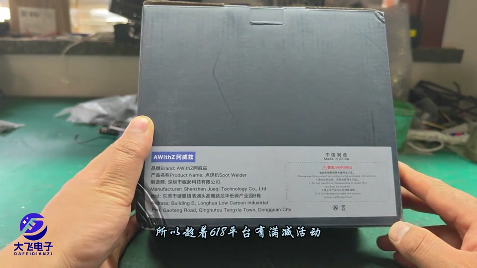
The creator rates AWithZ as one of the better consumer-grade welder brands — solid build, looks and features, a bit pricier than DM; he picked up the shop’s value model, the UF20B, on the 618 sale discounts. In the box: the unit, a 220V power cord, a pair of welding pens, a small roll of nickel-plated steel strip and a sheet of sandpaper. The unit is 18 cm long, 8 cm wide, 9.5 cm tall; the front has a display, two function keys and two 8mm welding-pen sockets (universal 8mm rubber plugs). The small socket next to the negative port is the manual trigger for the supplied pens; the universal trigger port on the right takes a foot switch or a one-piece welding pen. The back has a vent grille with a built-in fan cooling the MOSFETs, capacitors and power supply; a notch along the bottom edge plus an L-shaped power plug on the side mean it still gets airflow when stood upright. It’s a dual-supercapacitor 6V machine with a 1750A peak; it can weld 0.4mm nickel-plated steel strip but needs flux for that. After plugging in, give the capacitors a moment to charge — it’s quick. The pins are 1.5mm alumina copper, suited to 0.2mm nickel strip. Test welds on nickel strip held very firmly, and stainless steel was no problem either. Conclusion: a spot welder is a must for building lithium packs, and this one is a good choice.
 A must for battery welding: a solid weld in 1 second, plus how to stack the sale discountsProjectsDafei Repair
 LV2
LV2
16 × 15Ah LiFePO4 cells in 16S1P for a 48V e-bike battery, the full 30 minutes: nickel strip stacked on copper, a self-built welder that overheated and stopped work, a 60V/20A Bluetooth BMS, 16.5A measured on the bike
The creator builds a 48V LiFePO4 battery for an e-bike that has run on lead-acid for three or four years: 16 × 3.2V/15Ah cells all in series come to exactly 48V. To carry more current he stacks copper strip on nickel strip, and first tries two machines: the self-built welder welds 0.12 nickel-plated steel strip + 0.1 copper, the handheld welder welds 0.12 + 0.05 copper, both solid, and he mainly uses the self-built one (it can weld thicker copper). All 16 cells read 3.297V with 1.7–2mΩ internal resistance, so he builds without balancing. Triple holders are assembled (one holder with four extra corners wouldn’t fit and got trimmed), insulating paper applied, nickel and copper strip 15mm wide, the nickel strip’s sharp corners trimmed on the positive side; the jump starter that powers the welder is put on charge. During welding the self-built machine (with added capacitors, shortened leads and swapped MOSFETs), its thermal pad, the jump starter and the cells all get too hot to touch, so he keeps stopping to cool them with a fan; the jump starter won’t charge at 5V2A, so he pulls the 60V/20A Bluetooth BMS (switchable NMC / LiFePO4) from a previous 21700 pack. After several ‘won’t weld’ episodes he finds he had stacked two layers of copper by mistake; later he adds nickel strip to compensate. Main + to main − reads 52.7V, total internal resistance 32mΩ. 704 silicone to fix, mesh double-sided tape for the ribbon, sense leads soldered group by group and tinned (‘nearly had an accident’), lead order checked, 3 hours 40 minutes in total; the Bluetooth app gets LiFePO4 settings: over-voltage 3.65, under-voltage 2.3, balancing from 3.5; insulating board, main positive and temperature probe go in, insulating paper on, and heat-shrink film can be done with a hair dryer (keep it out of the sun). Lead-acid measures 89mΩ for comparison; the battery bay is bigger than expected (would take 48V30Ah); adhesive-lined heat-shrink for waterproofing; on the bike the app shows 53.0V, -16.5A, 14.8Ah, 0.038V delta, 0.9kW. LiFePO4 isn’t ideal for northern winters, but it’s cheap, safe and fades less than lead-acid. The top comment says the video is too long.


 Built a 48V LiFePO4 battery for the family e-bike myself — the whole process on record, in a mere 30 minutes of videoProjectsTechHang
LV2
Built a 48V LiFePO4 battery for the family e-bike myself — the whole process on record, in a mere 30 minutes of videoProjectsTechHang
LV2
Re-celling a fan’s old bank-terminal laptop: the original 6 × Samsung 2600mAh cells were badly unbalanced and dead, swapped for 2900mAh cells spot-welded with the handheld welder — no board lock, charging normal
An old bank mobile-terminal laptop (card reader, fingerprint) whose battery only showed 4% and would not climb. The creator had turned down re-cell requests before because “brand laptops lock the board when power is cut”, but this battery was already dead, so it was worth a try. Opening the pack: Samsung cells, total voltage looked normal, but per-group readings were 1.790V / 3.395V / 4.11V — left too long, badly unbalanced, scrap. New cells are 2900mAh (original 2600), internal resistance all around 19mΩ; the BMS has current sensing and will limit, so extra capacity would go unused anyway. With the new handheld welder (light) he tried gears 2 through 5 on nickel strip; the whole cell can is negative so no spacer is needed, the positive end gets insulating paper. Along the way: the layout shorts easily, the nickel strip is sharp, and with no jig it is awkward to handle — the three-cell junction was a struggle. Reinstalled, the laptop booted straight up, charge went 6% → 7%, and it did not lock the board after a power-off/on; he cleaned the old glue, checked balance (very consistent), fixed the temperature probe with 704 silicone, and rubber-banded it for a day while the glue cured. Later it showed 0% for an hour (suspected conflict with the BMS); he used the powercfg battery report to read the capacity history. A comment warned that re-celling may still need the battery-management chip (BMS) data reflashed.
 Fixing a fan’s laptop battery that died in storageProjectsTechHang
LV5
Fixing a fan’s laptop battery that died in storageProjectsTechHang
LV5
A ¥20–30 DIY fast-charge power bank with an honest rating: 8 × 2000mAh 18650 all in parallel for 16000mAh + a ¥10-ish boost fast-charge module + a PVC-sheet case
The heart of it is a power-bank boost module with a digital charge readout and fast-charge protocol support (about ¥10), paired with 8 × 18650 (¥2–3 each). Test the cells’ internal resistance, stick fish paper on the positive ends, load them into a single-row holder and wire everything in parallel (the module is a boost type, so it only needs 3.7–4.2V); 8 × 2000mAh = 16000mAh. Wrap in fish paper, spot-weld, insulate the positive and negative ends again with fish paper, measure 3.6–3.7V, solder leads onto the positive and negative pads and wrap the joints with filament tape. Two wires go to the module; press the switch and it shows the charge level. The case is hand-cut from PVC sheet (a 3D printer would look nicer), openings cut with a home-made fret saw and a small electric saw, glued with strong adhesive, with cut-outs for the display, the USB / Type-C ports and a small button. The Type-C port does input and output; with a powerful enough charger it goes into fast charge (green lightning icon), the USB port also fast-charges, and it will keep a phone going for two or three days.
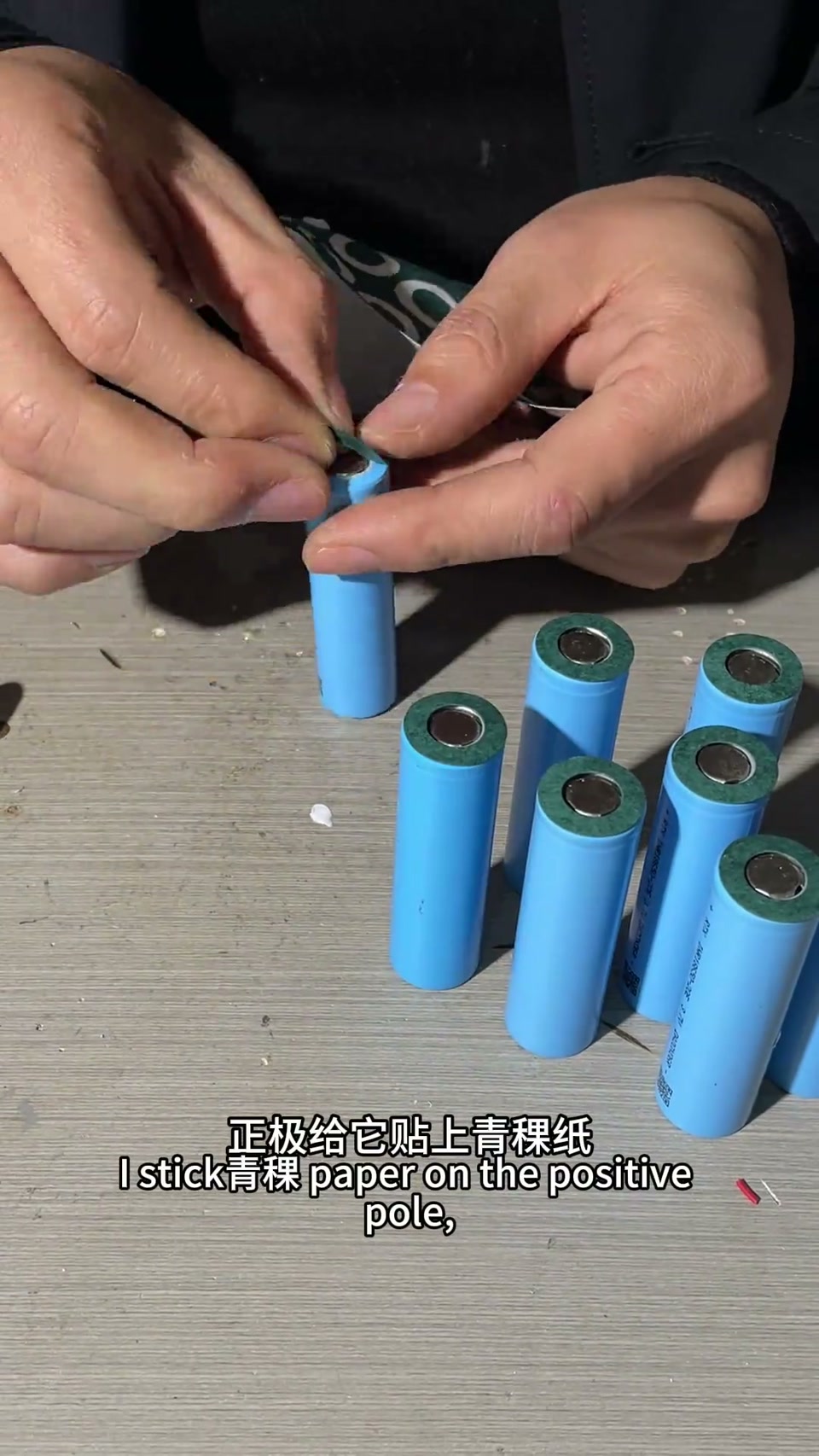

 Ep. 37 | A high-capacity power bank this easy? Build one at home for ¥20-odd — a huge-capacity, honestly rated power bank worth ¥100+ProjectsRural Abiao
LV5
Ep. 37 | A high-capacity power bank this easy? Build one at home for ¥20-odd — a huge-capacity, honestly rated power bank worth ¥100+ProjectsRural Abiao
LV5
¥1 junkyard speaker turned into a wireless Bluetooth speaker: the original amp board won’t amplify the Bluetooth signal, so the Bluetooth board drives the speaker directly + 6 × 18650 cells
An old powered speaker picked up at the scrapyard (under ¥1); fuse good, a hum on power-up, transformer output normal. The plan was to feed the Bluetooth module’s audio output into the original board’s audio input, but it didn’t amplify; switched to driving the speaker straight from the Bluetooth board, which works. So everything original except the driver comes out and it becomes rechargeable — 6 × 18650 spot-welded into a pack with a 3S60A balancing BMS, fish paper insulation and fibre tape; a diode and a CC/CV buck module on the charge side; a fast-charge port, charge-level display module and switch in the case; wired up, powers on, back in the case, phone pairs and plays, ‘sound quality is decent for its size’. The top comment points out that without audio amplification the result is only so-so.
 Ep. 36 | A Bluetooth speaker bought for under ¥1 sounds amazing after the mod! A junkyard speaker turned into a wireless Bluetooth speaker — the result is a real surpriseProjectsRural Abiao