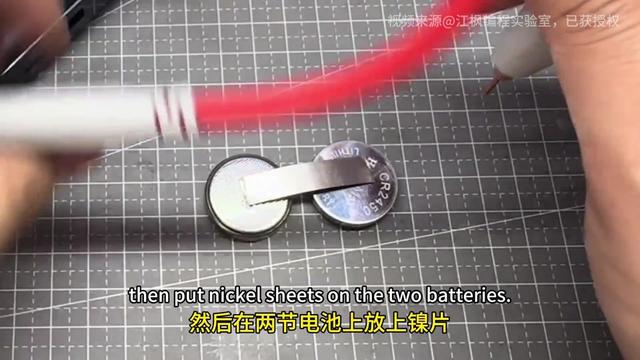
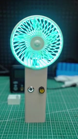
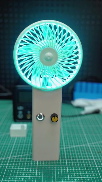
DIY monster fan | Hardcore conversion of a drone brushless motor into a monster fan🔥 Step-by-step tutorial, a spot welder builds super-strong airflow💨, enough wind to take off — the summer cooling wonder!
#AWithZSpotWelder #UF20BSpotWelder #MonsterFan #DroneMotorMod #diy
Avoid the pitfalls in 1 minute! Beginners building a pack — 3 steps solve the core problems: set the series count ➜ set the parallel count ➜ lock in the BMS. With the AWithZ H2-2026 handheld, even a newbie can weld a finished-grade pack and get safely to the end🚗 #AWithZSpotWelder #BatteryMaking #DIY #BeginnerGuide #PitfallGuide
Abiao hand-builds a portable rechargeable mini drill press (11 minutes, open-sourced on MakerWorld): 795 motor 12–24V, 20/60-tooth pulleys, tapered / linear bearings, shafts, 3D-printed parts; 6 × 18650 2600mAh 10C in 6S + 35A balancing BMS + IP2369 45W 2–6S charge/discharge module + meter + rocker switch, one balance lead per series group, first power-up needs 2–3V extra to activate, 21V output; v1 had the tapered bearings fitted the wrong way and melted from friction, remodelled and perfect: square steel cut like tofu, threaded rod drilled most of the way through
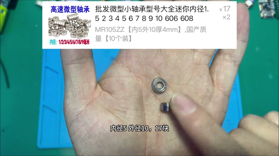
He had a set of pulleys but no mini drill press, so built a portable rechargeable desktop drill press with no cord; drills square steel like cutting butter and even large threaded rod. Materials list (with prices): 795 motor 12–24V ¥28.9, drill chuck + 5mm adapter ¥15.28, 20/60-tooth pulleys ¥12.1, two tapered roller bearings (10mm bore) ¥10, linear bearing ¥5.5, flanged linear bearing ¥15.2, 10mm shaft 40cm (¥17.5/m), 5mm shaft 10cm (¥39.9/10), M6×90 hex socket screws ¥3.73/5 sets, small 5×10 bearings ¥17/10, springs ¥4.3/10; electronics: 6 × 18650 2600mAh 10C (¥343 per 100), 6S 35A balancing BMS ¥23.74, DC 7–100V charge meter ¥10.9, IP2369 PD 45W 2–6S charge/discharge module ¥21.3, 6mm rocker switch ¥1.9; if you don't want Li-ion, skip the cells and BMS and run direct DC; if you don't have a spot welder and other professional tools, better not build a Li-ion pack. Battery: main positive and negative brought out on nickel strip to the BMS; many people struggle with balance leads, just remember: from negative to positive, one per series group, sampling each group's voltage; fit the balancing BMS and spot-weld the negative, plug in the balance leads; some BMS boards need an input 2–3V higher than the pack for a second or two on first power-up to activate; measuring around 21V output means it's active. Mechanical parts modelled to size, free and open-source on MakerWorld, PLA printing takes four plates and a dozen-odd hours, ¥20-odd in filament. Assembly: cells into the box recess, fit the charge meter, main positive reserved as a lead, charging module glued in at the Type-C cutout; meter negative, charger negative and main output negative all go to the BMS negative output; BMS charge input lead to the charging module negative, the other to the module positive, flick the module's little switch and the light comes on, working normally, Type-C both charges and can discharge to a phone; the pack positive's other lead goes to the switch's centre pin (input); output load lead, meter positive and sense lead twisted together onto the switch output; switch into its reserved hole; power on, meter lights up, close the lid; tap the shaft into its round hole. Head: small bearings top and bottom, tapered bearing (10mm bore printed adapter down to 5, tight space makes it a struggle to fit, a design failure), drill-bit adapter, flanged linear bearing with 4 screws, the other linear bearing, chuck, motor bracket with 4 screws, motor, small pulley grub screw, belt (better to fit the belt before the pulley); turntable base with two screws, loosen/tighten to adjust table height; the bottom clamp's third set of hex screws adjusts bit angle; springs on the two vertical rods; the handle's pivoting link copies an old hand-pump well, copper wire through the outer hole to stop it slipping off; power leads to the motor, dust cover. Test drill: after one hole it wobbles and vibrates badly, the shaft isn't vertical, the head model has a serious problem; taking it apart shows the plastic already fused and scorched; while drilling the bit pushes upward, rubbing the plastic until it heats and melts; remodel so the tapered bearings go in from the outside, one top and one bottom, stopping upward push and downward drop, the bearing inner race spins with the bit without rubbing; found that the small bearing's 10mm OD works as a reducer for the 5mm shaft; nearly two hours to reprint, fitting difficulty and friction heat perfectly solved; square steel like tofu, threaded rod not quite all the way through but close, good enough for a desktop mini drill press. Comments: made one too (4); don't cost it at 10cm, nobody sells 10cm; how much do you spend a month on inventions; add a fixture to turn beads; make it waterproof to cut bottles; main column too thin and too many plastic parts, poor rigidity, fine for fun; the rear column needs a really thick tube; can you make a mini table saw (tutorial coming).
Abiao from the village DIYs a portable rechargeable belt grinder for knives (903 likes): belt-grinder head kit ¥44 + 795 motor ¥28.9, a heat-shrunk bushing to fit the shaft, 3D-modeled and printed base / housing / motor bracket (promised open source); battery 9 × 18650 2000mAh 5C (¥3 each) in 3S3P 12.6V 6000mAh, nickel tabs spot-welded in a “box” pattern for the parallel / series joins so the balance board works, fish paper on, 3S 60A separate-port balance BMS ¥6.1, Type-C charging module ¥11.8, battery meter ¥10.9, latching lit button ¥6.9, 6-pin rocker switch for forward / reverse, ¥15.3 buck-boost stepped up to 24V to make the 795 more brutal; total cost ¥100-something; sharpens well; comments: isn’t the bottom of a bowl good enough, add a rest to fix the angle, does dry grinding anneal the edge (no)
The kitchen knife is blunt; experts use a whetstone, I’m a novice, so build a portable rechargeable belt grinder: forward / reverse adjustable, charge display, a neat power switch, stepless like a gas pedal; kitchen knives and machetes come up sharp with a quick pass, belts are swappable, one minute and it cuts vegetables like tofu; cost ¥100-something. Core parts: belt-grinder head kit ¥44 (comes with 5 belts, drive wheel / idler); 795 motor ¥28.9 (with mount and dust cover, 200W). Assembly problems: the motor shaft is smaller than the drive-wheel bore, so buy 5mm ID / 8mm OD bushings (¥19.5 for 5), heat the drive wheel so it expands and drop the bushing in, then lock the grub screw to clamp the motor shaft; the frame holes don’t line up with the motor holes and can’t be drilled (the original design wasn’t for a 775/795), so he models a base and housing (with battery bay and slots for the electronics) plus a motor bracket, 3D prints them, and will release the models free and open source; two screws hold the bracket to the motor, the other side to the steel frame, drive wheel fitted; changing a belt means removing the idler; a quick power-up to fine-tune the idler until it runs smooth. Battery: for portability, 18650 2000mAh 5C-discharge at ¥3 each, 9 cells for 12V (3S3P, 12.6V 6000mAh); battery meter DC7-100V ¥10.9; forward / reverse via a KCD1 6-pin 3-position rocker switch, ¥13 for 10; Type-C 3S charge-management module ¥11.8. Spot-weld the nickel tabs on; note the parallel / series joins are welded in a “box” pattern so the balance BMS actually works, otherwise it only balances one group; wrap in fish paper for insulation and heat isolation; fit the 3S 60A 12.6V balance BMS (¥6.1) — separate-port, so both input and output leads must be connected; pack goes into the printed box, input side to the Type-C charging module, plug in and it charges normally. Fit the lit metal latching button ¥6.9: switch input to the pack’s output positive; button negative and meter negative twisted into one lead; meter positive, sense lead, switch output and switch positive twisted into one lead; the negative lead to the pack’s output negative; into the input of the adjustable buck-boost module ¥15.3, then the master switch; the light comes on, so the wiring is OK. Forward / reverse rocker switch: the middle pins are the power input, and whichever of top or bottom is used as output needs two jumpers crossed to the other side’s pins — the principle is simply swapping positive and negative; switch input from the buck-boost output; the buck-boost raises 12V to 24V so the 795 is more brutal and spins faster; not building 24V directly because 12V is smaller, portable use doesn’t need long runtime, and 12V parts are in stock. Output leads out of the box to the motor; lid on; the frame bottom is screwed to a bracket and strong glue fixes the frame to the box base; motor positive and negative connected; job done; test grind works really well and fast, usable for DIY too. 102 comments: this is the way, no argument (7); is a 12V motor enough? why forward / reverse for sharpening? sourcing (2) → every part has detailed sourcing info in the video; where to buy components / is LCSC reliable (2); add a rest to fix the angle (1); an angle grinder takes seconds → too aggressive, the edge quenches; does dry grinding anneal it → no; isn’t a bowl bottom good enough (many); wasn’t this on your livestream → yes; posting at 4 a.m. → afraid of copycats; which 3D printer; the kit is only ¥40-something, don’t rip people off; help fix two streetlight lithium packs.
A Biao’s ‘New Year atmosphere machine’ (17 minutes, 4038 likes, MakerWorld / code open-source): scrap steel pipe and rebar welded into an angle-adjustable five-shot firecracker rack with rubber-band auto-feed; voice module (ASR-PRO) → ESP8266 transmitter over WiFi → ESP8266 receiver (700-line config web page) → relay → 24V high-voltage arc igniter; the 24V pack is 6 old salvaged 1500mAh 18650s spot-welded in series (24.63V), the 6S 35A balance BMS needs 26V to activate, CC/CV buck-boost charging at 25.2V, XL4005 stepping down to 5V for the MCU; the transmitter runs on an 18650 + 5V common-port module; live test: ‘fire!’ and it fires in sequence
Opens with ‘Second Battalion Commander, your Italian cannon’. The romance the New Year deserves: walkie-talkie in hand, set off firecrackers remotely by voice, load 5 at a time for burst or single shots; materials are scrap steel pipe and rebar plus a few dozen yuan of electronics; the principle is a WiFi transmitter and receiver controlling ignition. Mechanics: cut pipe and weld a rack, a pivoting joint at the bottom to adjust the angle, a tail so it stands stable; the front support uses old rebar and galvanised pipe, also adjustable; firecracker clip: slot the pipe for the clip bracket, weld a slide on the short end on the other side, weld as many pipes onto the base as shots you want (5), weld nuts at the head and the slide’s tail, cut a fuse groove in the pipe; the clip rides the slide, a rubber band through the screw hole anchors to the base, and after ignition it springs to the next one for automatic feed. Electronics (with shopping screenshots): one 2000mAh 18650 (¥3) powers the walkie-talkie (transmitter) with a 5V charge/discharge module (¥2.85); 6 old salvaged 1500mAh cells make the 24V pack with a 24V 6S balance BMS (NMC 6S common-port 35A with balancing, ¥25.74); a CC/CV adjustable buck-boost module (¥15.3) charges the pack, 5–30V wide input; an XL4005 adjustable buck module (¥5.5) takes 24V → 5V for the MCU; a USB port powers the ESP8266; 2 × ESP8266 (¥13.94), one transmit, one receive; ASR-PRO voice-recognition dev board (¥26.2) + small speaker; 5V relay module (¥2.9) switches the ignition; 24V high-voltage ignition kit (high-frequency transformer, two pins produce an arc). Programming: the voice module uses the vendor’s Chinese block-based tool, wake word ‘Second Battalion Commander’, commands ‘bring up my Italian cannon / fire / open fire / launch / stop / continuous fire / stop continuous fire’, sent over serial to the ESP8266, with synthesised voice generated in the model and flashed; the transmitter ESP8266 in VSCode PlatformIO: opens a hotspot + TCP server, relays the voice serial data, reconnects on drop, 300-odd lines; the receiver connects to the transmitter and handles ignition / auto cut-off / continuous fire, with its own hotspot serving a phone web page for settings (cut-off time etc.), 700-odd lines; flash and test via serial log. 3D-modelled boxes (ignition head, receiver box, transmitter box), open-source on MakerWorld for printing. Assembly: remove the ignition head’s HV leads, pass them through the box and re-solder, lengthen the power lead; the 24V pack is 6 cells in series, 25.2V full, 24.63V on the multimeter after spot welding, wrapped in fish paper, main + and − nickel tabs spot-welded on; balance leads run from the main positive, one per group in order; the balance BMS only takes the negative input and negative output, the positive bypasses the board and goes straight out; plug in the balance leads; the BMS is inactive by default and needs a moment of 26V+ to activate; voltage tests fine, boxed up, snug fit; the buck-boost output set to 25.2V and connected to a parallel pair of leads on the pack; the 24V output feeds the buck module set to 5V; forgot a switch, so cut the lead, extended it and added one; 5V leads to the USB socket; the relay also needs 5V, taken from the 5V buck; the buck-boost output also feeds two 24V leads, positive through the relay to the ignition head; relay 5V + IN signal + 24V in/out extended to the ignition pack, controlled by the ESP8266 high/low level; fit the ESP8266, Type-C power, aviation-connector socket as the charge port; power-up test — charge LED on, the switch wiring doesn’t smoke, manually triggering the relay gives a normal arc, receiver done. Transmitter: the voice module’s two serial wires go to the ESP8266 serial with RX/TX crossed; 18650 + 5V common-port module, nickel tabs spot-welded onto the cell to make soldering easier, then + and − leads soldered on and into the module input, Type-C charging with green flashing for charge and blue for discharge; two Type-C leads with + and − paralleled into one input, plus a switch (one end to 5V +, negative straight through, switch output to the Type-C +); fit the ESP8266, speaker on the lid, voice module, Type-C common-port module; the two Type-C leads feed the voice module and the ESP8266; power-on test, ‘fire!’ OK; lid on, a decorative ‘soul antenna’; phone into the config page to set auto cut-off time / continuous fire; the ignition head is fixed to the rack with an acrylic sheet for insulation, ignition pins glued so the arc lights the fuse; outdoor test, ‘fire!’, fires in sequence, works really well. 257 comments: does this count as manufacturing a firearm (an entertainment toy, not a weapon); I’ve only programmed 8266 with Arduino, can I learn this (absolutely); how to program it (follow the video); a rotary-drum launcher would be perfect (sold online); is it open-source; the pipe has no rifling; won’t the police have a word; are you selling, how much; fireworks are banned.
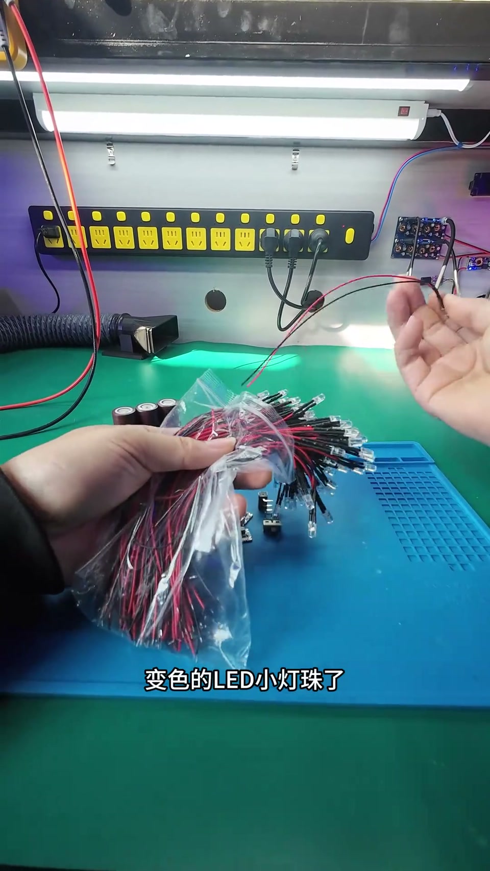
Abiao builds color-changing night lights for his students (2222 likes): one 2000mAh 18650 + charge-management module (Type-C, 4.2V charge, 5V output) + switch + 0.01A color-changing LED, runs a month; nickel strip welded to +/− and folded flat, tape to secure; modeled and 3D-printed shells, three sets in 4 hours; given to the best students in the last maker class of the term; comments: no BMS, aren’t you afraid the kids blow it up? link for the LED?
Somehow ended up making a few fun color-changing night lights / mood lights as a gift for the students who took a term of the science maker extension class — a little present for the last lesson, tied to what we covered. Simple parts: a cell, a charge-management module, a switch and a color-changing LED bead; the LED draws only 0.01A, so one 2000mAh 18650 keeps it lit for a month; the goals were long runtime, fun color changing, durable, rechargeable, simple and cheap to make. Build: nickel strip is already welded to the cell’s +/−; fold the strip over so it doesn’t stick out, and a wrap of tape around the outside makes it more secure; the cell’s +/− go to the charge-management module, charged over a Type-C cable, the module charges the cell at 4.2V; the module’s 5V output goes to the +/− leads; the LED negative goes straight to the output lead, the switch sits on the positive side; test lit fine, decent brightness; loose parts look untidy, so model a shell, one print run of three sets takes over 4 hours; the two halves fit together seamlessly; three done (short on time). Over hills and around eighteen bends to the school; in class every student gets hands-on, small hands not yet skilled but earnest, helping each other, completing the circuit together and lighting their first light-controlled lamp; maybe one day this light will shine among the stars; the lights he made go to the best students; applause closes the last lesson. Comments (143): where to buy such a low-power LED, link? (5); Biao, when’s the next spot-welder sponsorship (why?); a cell must have a BMS, safety first / no BMS, aren’t you afraid the kids get blown up (creator replied); the charging port sits too low to plug in easily; a white shell would diffuse the light better; what brand of multimeter (ALIENTEK); how’s the welder / how much.
[Welding test] UF20B: palm-sized, with the strength of a thousand pounds. 0.2mm pure nickel sheet on an 18650 pack, solid welds, energy focused in an instant #AWithZSpotWelder #diy #CompactSpotWelder #GeekMods #ElectronicsHobbyist
[Unboxing moment] UF20B — a professional power station in your palm. No preheat needed, one-button stable welding, easy spot welding, enjoy the assurance of every precise weld! #AWithZSpotWelder #diy #CompactSpotWelder #GeekMods #ElectronicsHobbyist
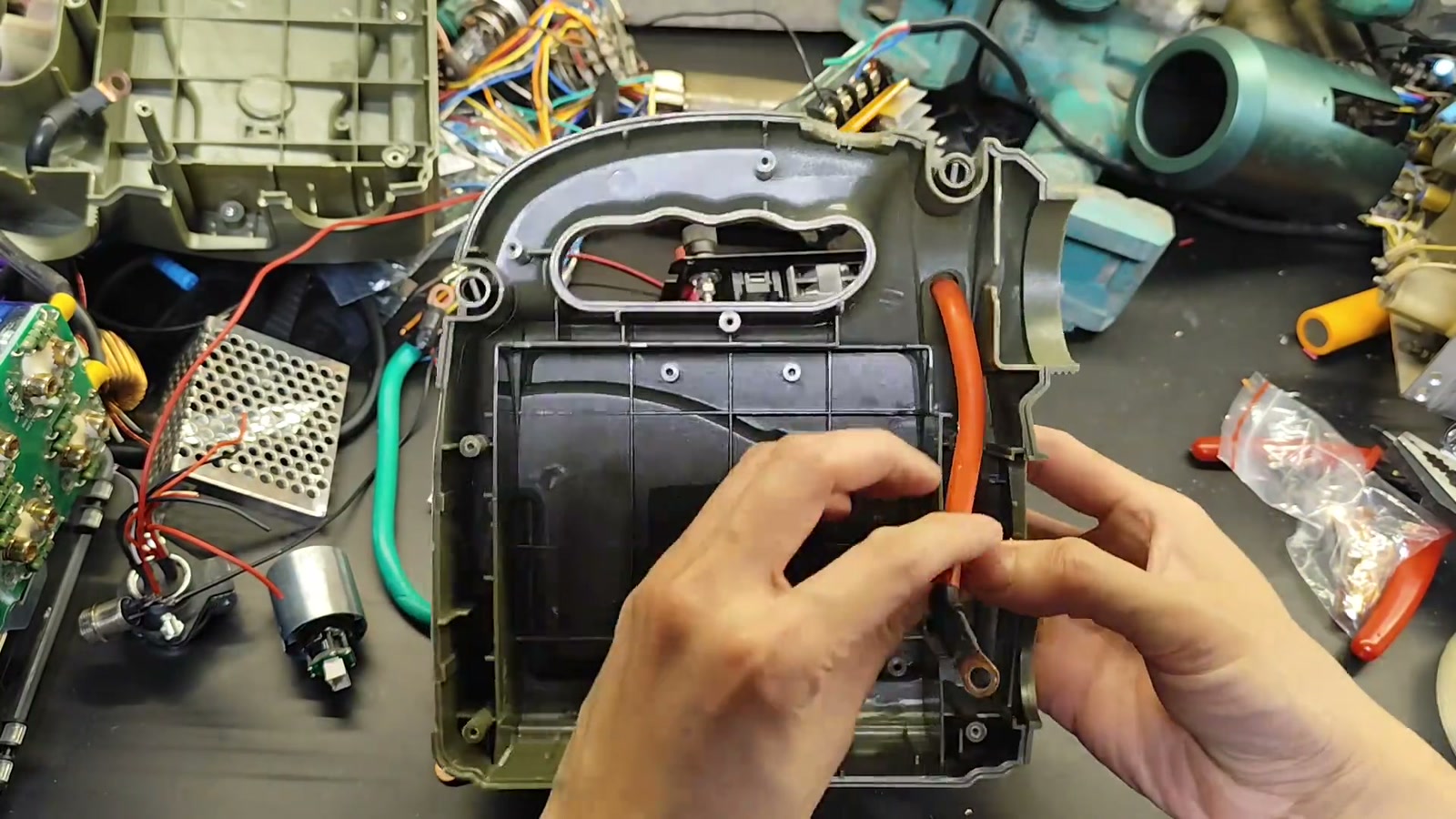
Supercapacitor + lithium jump starter (part 1): strip the original unit and re-plan the layout, remove the high-resistance main switch and replace it with a cell-to-capacitor switch, put lugs on the 25mm² leads, measure capacitor internal resistance 2.7 / 2.1; 10 × 21700 4000mAh, 2P4S, spot-welded with the AWithZ; oven paper as a heat barrier so thermal runaway can’t short; foam padding; shorting the cells straight onto the 0V capacitors draws 40-odd A (85A per the comments), clamps glow red — conclusion: must pre-charge through a resistor
Step one of the jump starter is stripping it down and re-planning the layout: wide at the bottom, narrow at the top, so the cells can only stand upright; turn the capacitors so the leads go straight out, shortening them to raise output current. The original board’s wiring was a mess and mediocre quality, so it all comes out; the original main switch has very high internal resistance, so it’s removed and replaced by a switch between the cells and the capacitors — flip it and the capacitors charge, no current limiting because the capacitors are small (big capacitors and you wouldn’t need the cells at all). The original wire is solid stuff but wasn’t secured after connection, so it made poor contact. The case cabling is nice and long enough; + and − are reversed to match the capacitor polarity; wire about 5mm dia., 25mm², re-routed with length to spare; crimp the +, and add a lug to the short − lead. Remove the original BMS and measure supercapacitor internal resistance: one 2.7, the other 2.1, slightly unbalanced. Crimping lugs: not a single strand showing, crimp one side then the other, drive the force at an angle from one side to the other, use a huge amount of force so it’s tighter than stock; with no heat-shrink this big, wrap in black tape leaving only the capacitor contact area bare. Trial-fit the −: enough room, enough slack; the cells can only go in this way, switch back in place, layout solved. There are 10 cells: 12 would make 3P4S, 10 only makes 2P4S; the spot welder joins the pairs in an instant, then three upright and one across to link them in series; oven parchment (forgot the fish paper) between them because it withstands heat, so a thermal runaway won’t short straight through — heat-shrink peels off when hot and shorts both faces; jokes that his poor welding is ‘wasting the cells AWithZ sent’. Voltage fine after welding; balance leads connected (smarter to bring them straight out); tape over the welded face against punctures, then fish paper; BMS wired (an odd shape, roughly done): two thin leads charge / discharge through the BMS, two extra-thick leads short-charge the capacitors instantly. Foam padding in the case so the capacitors sit firm and a drop won’t be too dangerous; lid snaps on tight, slight wobble to fix later. Charging-circuit test: cells shorted straight onto the 0V supercapacitors, clamps glow red, current hits 40-odd A — too dangerous, could blow, must pre-charge through a ceramic resistor and only then close the shorting switch in parallel and start. Comments: someone built 3S5P 18650 + 6 × 500F in series and it struggles to start a 2.0T (creator: voltage too low, needs 4S at 16.8V to fill the capacitors); the copper lugs are sloppy; capacitor internal resistance too high; a local warns the capacitors are too small for winter (creator: couldn’t bring himself to buy big ones, not the optimal solution).
Who gets the joy of a one-second fuse? 32140 LiFePO4 power cell with 0.25 copper, welding test, P60F all-new supercapacitor spot welder
#diy #WeldingEquipment #Satisfying #Tech #GoodFinds
This is how a perfect weld on a 32140 LiFePO4 cell is made! AWithZ UF20B spot welder — nails the hard welds with ease. #LiFePO4 #WeldingEquipment #diy #Tools
Don't throw away a dead power-drill battery! Fix it yourself with this 'portable wonder' and save more than half the cost! Small footprint, plenty of power. H1 handheld dual-pulse spot welder! #BatteryRepair #diy #Handmade #WeldingEquipment #PowerTools
P60F supercapacitor spot welder — the real-world test is legendary! 0.1mm nickel-plated steel strip + 0.2mm copper strip welded in a second, no spatter, super strong! #WeldingEquipment #GoodFinds #diy #Tools
Dapao Meimei in 24 seconds: strips the motor from dad's vacuum, a ¥2 air-conditioner drain hose heat-gunned onto it for a solder-fume extractor, a ¥6 Li-ion cell with internal resistance 18, AWithZ UF20B plug-in spot welder 'the perfect spot weld', a red wire to start it — hold it a bit further away and it can't pull the fumes at all, worse than a little fan
Solder fumes are bad for your health, so just build an extractor: strip dad's vacuum cleaner for the big motor; buy an air-conditioner drain hose for two yuan, heat the end evenly with a heat gun and gently slide it over the motor's intake; the newly bought six-yuan Li-ion cell has internal resistance 18, not bad; a burst of gibberish welding, very dashing — AWithZ UF20B plug-in spot welder, the perfect spot weld (screen shows a W318000 reading); finally run a red wire between the cell and the motor, the perfect weld; fire it up and test, looks fine, hold it a bit further away and it can't pull the fumes at all, worse than my little fan. 311 comments: 'for the perfect weld skip straight to 17 seconds if you're in a hurry' (pinned); dad: well thank you very much (he's working late and not home yet); a violent fan pulls fumes so fast (where can you strip a violent fan from); switch lanes (you recommend one and I'll follow); first time seeing a girl into this.
A power bank making a power bank? The U3 Pro spot welder welds 0.35mm with no sweat! For a small spot welder, pick AWithZ #WeldingWonderTool #GeekMods #ElectronicsHobbyist #diy
[AWithZ P60F | The sure-profit choice for batch production]
Continuous welding that never drops a beat, handles 0.2mm nickel-plated steel strip with ease — efficient volume production of 21700 packs! A great money-making helper!
#ForCompactSpotWeldersChooseAWithZ #WeldingTools #diy #Geek
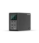
Precision spot welding, solid in an instant! A professional spot welder that's a step ahead in efficiency! One machine, many functions — save the cost of several devices! All-new P30C supercapacitor energy-storage spot welder #AWithZSpotWelder #WeldingEquipment #CapacitorBlackTech #ElectronicsHobbyist #diy
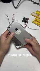
iPhone 6 modded to 20,000mAh: 4 × L700 (5000mAh) in 4P, nickel strip joined with an AWithZ spot welder, hot-glued to the back of the phone, a 45℃ thermal switch auto-starts a cooling fan
Turning a years-old iPhone 6 battery that only lasts half an hour into an external 20,000mAh pack. Teardown: open the cover plate, remove the battery connector bracket, pry the battery out with a spudger; drill a small M3 hole in the case, then widen and deburr it so it won’t cut the wire, and route the iPhone 6’s power flex through the hole to the back. First test with 1 L700 taped to + and −: no light the first time because the flex wasn’t clipped in tight; press it down and ‘3, 2, 1, on’, swiping works. Then the big battery: 4 × L700 (5000mAh each) in 4P = 20,000mAh; out comes the AWithZ spot welder, nickel strip joins the positives and likewise the negatives, with fish paper for insulation. The hot-glue gun first dabs the power flex so it can’t come loose, then the back of the phone is covered in hot glue to stick the battery on, both sides filled so it won’t wobble. A soldering iron tins the nickel strip and the wire ends, then solders + and −; it boots to the home screen, Wi-Fi works. Finally a 45℃ thermal switch (actual part marked KSD9700 50℃ 250V10A) is wired to a cooling fan, hot glue holds the switch and fan together, the switch’s + and − are soldered to the battery: once the case goes over 45℃ the fan starts by itself, no physical button. Camera and swiping work — done. Top-liked correction in the comments: charging without a BMS is very dangerous, a 21700 is 4.2V full while an iPhone battery is 4.45V; others worry the big battery will fry the logic board, and ask how to read the charge percentage.
Wuliao Chaixiu tests an AWithZ H1 sent by the factory: compact, 11 gears, long-press the side button to power on, short-press the top button for gear / long-press to switch auto/manual; 0.1 nickel strip at gear 1 pulls off by hand, at gear 5 with three taps it takes pliers to tear apart; 0.2 nickel strip comes off with a light tug at gear 5 and with a bit of force at gear 11 → no good; 0.15 on a cell at gear 11 needs pliers — ceiling is 0.15; compared with a DIY welding board at ¥40–50 + a DIY battery, ¥200-plus for the set and three have already died; suited to hobby DIY, don’t expect a ¥100-odd unit to handle heavy use
Another manufacturer sent a product to test: the AWithZ small handheld spot welder H1; AWithZ is a company that specializes in spot welders; compact, suits DIY, not expensive, worth buying if you weld only occasionally. Long-press the side button to power on; short-press the top button to change gear, 11 gears in all; long-press to switch between auto and manual. The 0.1 nickel strip that came in the box: at gear 1, one manual tap feels smooth, but a tug pulls it off by hand (the strip tears a little); at gear 5 with three more taps it can’t be pulled off by hand, and pliers tear it apart. 0.2 thick nickel strip: comes off with a light tug at gear 5, and at the top gear 11 comes off with a bit of force — 0.2 isn’t really doable. 0.15 nickel strip welded onto a cell at gear 11 can’t be pulled off by hand, pliers needed, quite solid; 0.1/0.15/0.2 all tried, the thickest it can weld is 0.15. The ¥40–50 welding board he bought before needs a high-discharge battery; the battery he built himself (doubles as a power bank / car jump starter) cost ¥100-odd, so ¥200-plus for the set, and it breaks easily — this is the third one; had he known AWithZ made these he wouldn’t have bought that; the H1 suits hobby DIY, but if you weld a lot and hard, don’t expect ¥100-odd to meet your needs. Comments: the free one is great, the one you buy isn’t (7); low needs, a few small packs now and then, just right; the battery type has too little current, you still need a capacitor (creator: this one only sells for ¥100-odd); officially rated for 0.25 (there’s fine print); only two MOSFETs on the board, no good; 0.15 won’t weld at all, only 0.1; this thing is no good, I bought one (creator: mine was free).
A must for phone addicts! Full walkthrough of a homemade 10000mAh power bank! U3 Pro spot welder, only grade-A cells. One unit, two uses: power bank + spot welder #ForCompactSpotWeldersChooseAWithZ #WeldingWonderTool #GeekMods #diy #ElectronicsHobbyist
Precise spot welding in the palm of your hand! H2 handheld colour-screen spot welder — welding with more freedom! #AWithZSpotWelder #WeldingEquipment #diy #UnorthodoxHacks
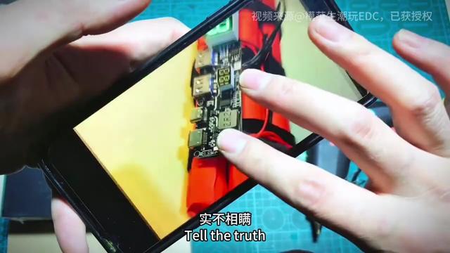
100W PD fast-charge power bank for under ¥100: 4 × Lishen L700 4000mAh in 4S, 16.8V (misspoken as 16000mAh), ¥70-odd case kit (100W multi-protocol board + 4S BMS + aluminium shell), Li-ion tape to hold, fish paper, AWithZ welder for the + and − ends, round welds, nickel strip and wire ends tinned first, thermistor under heat-resistant tape, 3M adhesive into the case; Samsung PD measures 19.5V × 3.1A ≈ 58W (66W cap), the seller didn’t oversell; can also feed a soldering iron to 400W for a few seconds
For under ¥100, a power bank with 100W output (kit rated 20000mAh 100W PD); Samsung PD tops out at 66W, measured around 60W; stickers for looks; also handy for powering a soldering iron up to 400W for a few seconds. Cells are Lishen L700, 4000mAh each, four make 16000mAh (corrected in the comments: in 4S the capacity is still 4000mAh). Materials: case bundle ¥70-odd including the 100W multi-protocol fast-charge board, 21700 4S BMS and aluminium alloy shell; four 21700 cells at about ¥5 each; fish paper; nickel strip (Maikedai); translucent charge-level sticker; plastic back cover. Build: four cells in series for 16.8V, Li-ion tape for a first hold; fish paper (front and back); out comes the old regular, the AWithZ welder, power on, weld the positive first, welding is super satisfying, beep-beep like arc welding, always keep + and − straight; 4S 4.2V to 16.8V, if the principle isn’t clear DM for the wiring diagram, reversed will burn out; fish paper after welding, tin the pads on the 16.8V BMS; solder the + / − jumper, welds must be round and full so the load spreads and they don’t pull off; BMS onto the cells, wire ends run under the tape for looks and to protect the wire; trim the strip corners so it fits in the case, leave a solder point, bend it by hand onto the pad and solder with the iron so the strip sits tight in the solder; back-side + / −, a dab of solder on the strip then a dab on the wire end is easier; 99% solder wire; trim the strip edges; tin the BMS + / − pads the same way (wire end not tinned, redo it); keep + and − straight; fish paper insulation; thermistor through and held with heat-resistant tape, it senses cell temperature to stop overheating on charge and discharge; cells and BMS into the shell, the seller includes 3M adhesive to stick between the two boards, tidy the wires as it goes in or it won’t fit, back cover on with two screws, wires not tidy so it sits a little proud and the screws have to pull it down; the shell has a front and back, stick on the dark protective shell, fit the bottom shell, done; lure-fishing and drone stickers (shouldn’t count as infringement). Test on Samsung PD 66W: 19.5V 3.1A ≈ 58W, the seller didn’t oversell, no 100W phone so 66W is the most it can test; next episode a 60000mAh one to charge a dozen phones. Comments: fake Lishen rewraps are everywhere, Pinduoduo worst of all (3); been using one for two years; how do four 4000 cells in series make 16000; what’s the board’s controller, Injoinic SW6306?; a colour screen would be nice; parts list.
Firefly’s ‘workhorse daily grind’: hooked on the U3 Pro, takes a cleaver to it to unwind, then gets to real work — CNC-milled copper tabs, 3D-printed four-hole holder, laser engraving, a 2S2P flashlight pack (Wurkkos SP10 and other 8.4V lights), multimeter check after welding, green heat-shrink; comments: 1mm copper plate won’t take a weld, no BMS fitted (stock has none either, a generic board won’t fit a flashlight), ‘even 1.5 nickel-plated is a struggle, badly over-rated, just returned mine’ (creator: no sponsorship money exists)
Opens with ‘I’m hooked, taking my ex’s cleaver to unwind, weld weld weld’, then ‘real work comes first’. Process (no narration, watching the footage): CNC-mill small copper tabs (comment: 1mm copper plate is a bit thick and won’t take a weld, hence small tabs); 3D-print a four-hole cell holder; caliper measurement; laser engraving; four cells (14500/16340-class small cells) go into the holder, the U3 Pro spot-welds nickel strip into 2S2P; multimeter reads about 7V (2S); green heat-shrink seals it into a flashlight pack that goes into a Wurkkos SP10-class 8.4V light; ‘open for business +1’. 73 comments: how much sponsorship did you take, even 1.5 nickel-plated is a struggle, badly over-rated, just returned mine (no sponsorship money exists); not even a BMS? (no suitable board, the stock battery has no balance board either, a generic board won’t fit in a flashlight, a small board trips output protection the moment the light turns on); thought you’d weld the copper on directly (1mm copper plate is a bit thick, won’t take a weld); CNC and Fluke too, the weak student has the most tools; will careless welding hurt the discharge cap’s life (liked by the creator).
One machine, many uses, formidable performance! H1 handheld spot welder unboxing + welding test — you'll want one after watching! #AWithZSpotWelder #diy #ElectronicsHobbyist #GeekMods #MoneySaver
Light and portable, a compact home welding wonder! H1 handheld dual-pulse spot welder makes everyday welding more efficient! #AWithZSpotWelder #WeldingEquipment #diy #GoodFinds #HighPerformanceTools
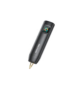
Uncle Jiang reviews the AWithZ U3 (Li-ion version, 11000mAh): palm-sized, 2-inch colour screen, USB / C ports can even reverse-charge a phone, welds 0.1 copper / 0.35 nickel-plated / 0.2 pure nickel, 80 gears from 1.0 to 9.0, auto mode with 0.5s trigger and 2 pulses, 40 cm thick-copper-wire pens with a front-facing opening, test weld on a coin cell — one ‘beep’ and done; ¥100-odd, good enough for DIY
The solar-lamp project needs lithium packs welded; a soldering iron is slow on lithium cells and a safety risk, so he bought an AWithZ U3 welder, the Li-ion version with 11000mAh (on-screen specs: 0.1mm copper, 0.35mm nickel-plated, 0.35mm steel, 0.2mm pure nickel) — not expensive, good enough is good enough; if you have more use cases, buy a more professional model. Looks: palm-sized; welding-pen socket top-left; 2-inch colour screen in the middle; two buttons on the right (adjust key, power / option toggle key); USB and C ports on top — the official notes say besides charging it can emergency-charge a phone, but inefficiently; manual weld key on the right (touch to trigger in manual mode). Long-press to power on into the main menu: battery and temperature in the centre, 6 sub-menus toggled by tapping, short-press the adjust key to change values; settings menu top-right (language, pulse interval, sound etc.), defaults are fine — the only thing to set is the gear: 80 fine gears from 1.0 to 9.0, matched to the material, neither too high nor too low. The pens use thick copper wire — low resistance, low loss, no heating; detachable alumina-copper welding pins are safe and durable; the handle has a manual weld key; the pens are 40 cm long with a front-facing opening to maximise usable length; line up with the socket and push in. Set the parameters before use: auto mode, 0.5s trigger, 2 pulses, gear starting at 3; test on a dead CR2032 coin cell with the material supplied by the manufacturer: hold one pen still, press the other down close by, the machine welds automatically with a ‘beep’; check the weld by prying with pliers to see how solid it is, and if the weld is weak, raise the gear until it’s perfect. Verdict: highly recommended for DIY battery or small-appliance welding. Comments: what price, where to buy, how to remove a welded joint without damage (creator: ¥100-odd; needle-nose pliers will get it off but leave marks); ‘I have this one too, ¥200-odd’.
Electric grass trimmer from scrap: galvanized pipe + steel plate + belt-driven 775 motor, powered by a 3S5P 18650 pack through a boost module at 33V
One end of a two-metre galvanized pipe is cut at an angle and a steel plate is welded on tilted about 45° (like a small hoe); a handle is welded on wherever it feels right. Four holes in the plate take two bearings (as close to one straight line as possible), a shaft goes in and the excess is cut off, then an adapter, clamp plate and small pulley are fitted. A bracket for the 775 motor is welded on; once cool, the 775 motor and belt go on, and a powered test shows it runs smoothly. For power, 18650 cells make a 3S5P pack with a balancing BMS, fitted into a box with input / output / gauge / switch holes cut in it; the charge input gets a CV/CC buck-boost module with charge management set to about 12.8V; the battery positive runs through the switch into a boost module set to 33V feeding the 24V 775 motor — more torque and more speed. The box is fixed to the tail of the pole, the output lead connected, a shoulder strap tied on and trimmer line fitted (soft wire for now). A test cut at the front door works well — lighter and quieter than a petrol trimmer.
Ran into a problem? Have an idea for improvement? Tell us. We read every piece of feedback carefully. Valid feedback earns points, redeemable for accessories / coupons.
Thanks for your feedback!
We'll review it within 1–5 business days. If you left an email, valid feedback earns points redeemable for accessories / coupons. If we need to follow up, we'll contact you at the email you left.
WeldWorld is an open platform for user sharing; content does not represent official advice.
Improper battery handling can cause fire, explosion, chemical burns and serious injury. Read the full AWithZ Safety & Usage Guidelines before any lithium battery assembly, spot welding or testing, and before using the community.
Community content is personal experience, not verified by AWithZ; where it conflicts with official documents, the official documents prevail.
Never apply someone else's settings directly; always start at a low level and test on scrap.
Before copying any procedure, go through the self-check list in Part 3 of the guidelines.
 LV5
LV5
 UF20B Supercapacitor WelderProductsAWithZ








 LV4
LV4






 LV1
LV1



 LV2
LV2



 LV1
LV1