
Building a car jump starter from supercapacitors + lithium cells — the cells store energy, the supercapacitors deliver the big current; 21700 4000mAh cells in 2P4S, 2.7V 360F supercapacitors, two together should push past 100A instantaneous, CCA estimated 500+, should start a 2.4L car; final assembly and test next


Creator’s own settings as stated in the video (timestamps link to the moment). Not official values — test on scrap first.
Bill of materials
Welder, accessories, consumables and parts used in this build; quantities and specs are editable Download BOMDescription
Supercapacitor + lithium jump starter (part 1): strip the original unit and re-plan the layout, remove the high-resistance main switch and replace it with a cell-to-capacitor switch, put lugs on the 25mm² leads, measure capacitor internal resistance 2.7 / 2.1; 10 × 21700 4000mAh, 2P4S, spot-welded with the AWithZ; oven paper as a heat barrier so thermal runaway can’t short; foam padding; shorting the cells straight onto the 0V capacitors draws 40-odd A (85A per the comments), clamps glow red — conclusion: must pre-charge through a resistor
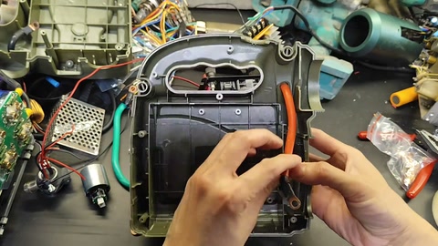
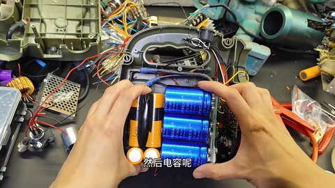
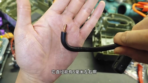
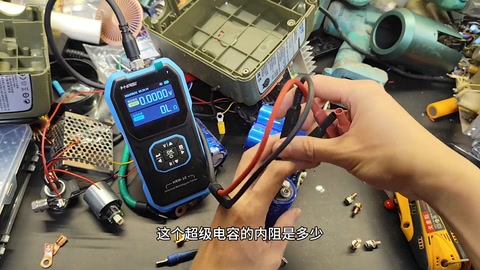
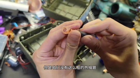
Step one of the jump starter is stripping it down and re-planning the layout: wide at the bottom, narrow at the top, so the cells can only stand upright; turn the capacitors so the leads go straight out, shortening them to raise output current. The original board’s wiring was a mess and mediocre quality, so it all comes out; the original main switch has very high internal resistance, so it’s removed and replaced by a switch between the cells and the capacitors — flip it and the capacitors charge, no current limiting because the capacitors are small (big capacitors and you wouldn’t need the cells at all). The original wire is solid stuff but wasn’t secured after connection, so it made poor contact. The case cabling is nice and long enough; + and − are reversed to match the capacitor polarity; wire about 5mm dia., 25mm², re-routed with length to spare; crimp the +, and add a lug to the short − lead. Remove the original BMS and measure supercapacitor internal resistance: one 2.7, the other 2.1, slightly unbalanced. Crimping lugs: not a single strand showing, crimp one side then the other, drive the force at an angle from one side to the other, use a huge amount of force so it’s tighter than stock; with no heat-shrink this big, wrap in black tape leaving only the capacitor contact area bare. Trial-fit the −: enough room, enough slack; the cells can only go in this way, switch back in place, layout solved. There are 10 cells: 12 would make 3P4S, 10 only makes 2P4S; the spot welder joins the pairs in an instant, then three upright and one across to link them in series; oven parchment (forgot the fish paper) between them because it withstands heat, so a thermal runaway won’t short straight through — heat-shrink peels off when hot and shorts both faces; jokes that his poor welding is ‘wasting the cells AWithZ sent’. Voltage fine after welding; balance leads connected (smarter to bring them straight out); tape over the welded face against punctures, then fish paper; BMS wired (an odd shape, roughly done): two thin leads charge / discharge through the BMS, two extra-thick leads short-charge the capacitors instantly. Foam padding in the case so the capacitors sit firm and a drop won’t be too dangerous; lid snaps on tight, slight wobble to fix later. Charging-circuit test: cells shorted straight onto the 0V supercapacitors, clamps glow red, current hits 40-odd A — too dangerous, could blow, must pre-charge through a ceramic resistor and only then close the shorting switch in parallel and start. Comments: someone built 3S5P 18650 + 6 × 500F in series and it struggles to start a 2.0T (creator: voltage too low, needs 4S at 16.8V to fill the capacitors); the copper lugs are sloppy; capacitor internal resistance too high; a local warns the capacitors are too small for winter (creator: couldn’t bring himself to buy big ones, not the optimal solution).
Outcome
| Goal | Supercapacitor + lithium jump starter, part 1: layout, lugs, battery pack, short-charge test |
| Build | 2 × 2.7V 360F supercapacitors + 8 × 21700 4000mAh in 2P4S + BMS |
| Result | Layout done, pack welded; direct short-charging at 40+A is too dangerous, so a pre-charge resistor is to be added · verified on camera: 483–523s short-charge test readings and conclusion |
Steps11 steps · click a frame to jump
 1. Strip it down, re-plan the layout, shorten the leads
Wide bottom, narrow top, so cells only stand upright; turn the capacitors so the leads go straight out, shorter leads for more output current; the original board’s wiring is a mess and mediocre quality, so it all comes out.
00:00 – 00:24 2. Remove the high-resistance main switch, fit a cell-to-capacitor switch (no current limit)
The original main switch jump-starts as soon as it closes, but its internal resistance is very high, so out it comes; replace with a switch between the cells and capacitors — flip it and the capacitors charge, no current limit because the capacitors are small (with big capacitors you wouldn’t need the cells); the original wire is solid but unsecured, so it made poor contact.
00:24 – 00:56 3. Re-route the 25mm² leads, reverse polarity, add a lug
The case cabling is long enough; + and − reversed to match capacitor polarity; wire about 5mm dia., 25mm²; re-routed with slack; crimp the +; the − is short, so add a lug to reach.
01:00 – 02:20 4. Remove the BMS, measure capacitor internal resistance 2.7 / 2.1
Remove the capacitors’ original leads and swap for clips; take off the BMS; supercapacitors have internal resistance too — measured 2.7 on one and 2.1 on the other, slightly unbalanced.
02:20 – 02:58 5. How to crimp a lug; black tape instead of heat-shrink
No strand showing; crimp one side, then fix the other; drive at an angle from one side to the other; use huge force so it’s tighter than stock; no thick heat-shrink, so bind with tape; same for the + end, can’t be pulled off; black tape leaves only the capacitor contact area bare.
02:48 – 03:52 6. Trial fit: the − reaches, cell layout fixed
With the − connected and everything back in place it’s very workable, enough slack, enough room; the cells can only go in this way; the switch lines up; layout solved.
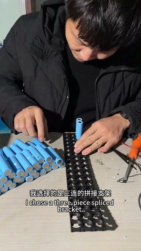
03:55 – 04:38 7. 10 cells only makes 2P4S; weld the pairs, then series
There are 10 cells; 12 would make 3P4S, 10 only makes 2P4S; the spot welder joins the pairs instantly; then three upright and one across to link in series; one side of the three-series done.
04:38 – 05:07 8. Oven paper withstands heat and stops thermal-runaway shorts; jokes about his welding
Oven parchment between the cells (forgot the fish paper) — heat-resistant, so in a thermal runaway the middle won’t short straight through; heat-shrink peels off when hot and shorts both faces; jokes that his poor welding wastes the cells AWithZ sent, needs more practice; welds the last series link.
05:07 – 05:49 9. Voltage OK; balance leads; puncture tape + fish paper; BMS and shorting leads
Voltage fine after welding; balance leads connected (should have brought them straight out); tape over the welded face against punctures, then some old fish paper; BMS wired, a bit rough; two leads charge / discharge through the BMS, two extra-thick leads short-charge the capacitors instantly.
06:00 – 06:56 10. Foam padding in the case, capacitors back in, lid snaps tight
Little padding originally, so add foam; the capacitors sit firm, a drop won’t be too dangerous; the lid snaps on tight, slight wobble to fix later; no rattling.
06:56 – 07:57 11. Short-charge test: 40+A, clamps glow red, must pre-charge
Cells shorted straight onto the 0V supercapacitors; clamps glow red, current hits 40-odd A; too dangerous, could blow; must pre-charge through a ceramic resistor, then close the shorting switch in parallel and start.
07:57 – 08:43
Bill of materials
| Original jump-starter case / cabling ×1 | 25mm² wire · Base for the mod |
| Supercapacitors ×2 | 2.7V 360F · High-current discharge |
| 21700 cells ×8 | 4000mAh, gift from AWithZ · 2P4S energy storage |
| AWithZ welder (U3) ×1 | Spot welding |
| Wire lugs / crimping pliers | Main lead connections |
| Oven parchment / fish paper / tape | Heat-resistant · Heat barrier, insulation, puncture protection |
| 4S BMS ×1 | Charge / discharge protection |
| Foam padding | Against knocks |
| Internal-resistance meter / power meter | Measurement |
Measured on camera
| Supercapacitor 1 internal resistance | 2.7 mΩ 02:33 |
| Supercapacitor 2 internal resistance | 2.1 mΩ 02:45 |
| Pack voltage | 14.66 V 07:57 |
| Short-charge current | 40-odd A 08:24 |
Creator’s tips
- Shorter main leads mean more output current; keep high-resistance switches out of the discharge path 00:14
- Crimping lugs: no strand showing, one side then the other, drive at an angle, press hard 02:45
- Put a heat-resistant barrier (oven paper / fish paper) between cells so a thermal runaway can’t short straight through 05:07
- Tape over the welded face against punctures, then cover with fish paper 06:14
- Add foam padding in the case against knocks 07:10
- Charging a 0V supercapacitor must go through a pre-charge resistor; close the shorting switch only once it’s full 08:17
Pitfalls
- The original wire wasn’t secured after connection and made poor contact 00:55
- The − lead is too short and needs a lug 01:24
- The two capacitors’ internal resistance doesn’t match (2.7 / 2.1) 02:45
- No fish paper to hand, made do with oven paper; balance-lead routing is clumsy 05:07
- Shorting the cells straight onto the capacitors draws 40+A and the clamps glow red 08:11
Li-ion safety
- Shorting straight onto a 0V supercapacitor draws far too much current and could blow; pre-charge is a must 08:24
- Heat-shrink peels off when hot and shorts both faces; a heat-resistant barrier is needed 05:21
- Knocks inside the case are a hazard; add padding 07:10
Quotes




Comment insightsanswered 3 · open 1 · corrections 3
Answered by the creator
Open questions
Corrections from viewers
I also built a Li-ion + supercapacitor combo, 15 × 18650 power cells in 3S5P, 6 × 2.7V 500F supercapacitors in series giving 16.2V 83.33F, fully charged it struggles a bit to start a 2.0T car but does start it, not as clean as 6 × 2.7V 3000F supercapacitors in series.
Reply @天亮SAY晚安:
I also built a Li-ion + supercapacitor combo, 15 × 18650 power cells in 3S5P, 6 × 2.7V 500F supercapacitors in series giving 16.2V 83.33F, fully charged it struggles a bit to start a 2.0T car but does start it, not as clean as 6 × 2.7V 3000F supercapacitors in series.
Reply @天亮SAY晚安:
I also built a Li-ion + supercapacitor combo, 15 × 18650 power cells in 3S5P, 6 × 2.7V 500F supercapacitors in series giving 16.2V 83.33F, fully charged it struggles a bit to start a 2.0T car but does start it, not as clean as 6 × 2.7V 3000F supercapacitors in series.
Reply @天亮SAY晚安: