Supercapacitor + lithium jump starter (part 1): strip the original unit and re-plan the layout, remove the high-resistance main switch and replace it with a cell-to-capacitor switch, put lugs on the 25mm² leads, measure capacitor internal resistance 2.7 / 2.1; 10 × 21700 4000mAh, 2P4S, spot-welded with the AWithZ; oven paper as a heat barrier so thermal runaway can’t short; foam padding; shorting the cells straight onto the 0V capacitors draws 40-odd A (85A per the comments), clamps glow red — conclusion: must pre-charge through a resistor
Step one of the jump starter is stripping it down and re-planning the layout: wide at the bottom, narrow at the top, so the cells can only stand upright; turn the capacitors so the leads go straight out, shortening them to raise output current. The original board’s wiring was a mess and mediocre quality, so it all comes out; the original main switch has very high internal resistance, so it’s removed and replaced by a switch between the cells and the capacitors — flip it and the capacitors charge, no current limiting because the capacitors are small (big capacitors and you wouldn’t need the cells at all). The original wire is solid stuff but wasn’t secured after connection, so it made poor contact. The case cabling is nice and long enough; + and − are reversed to match the capacitor polarity; wire about 5mm dia., 25mm², re-routed with length to spare; crimp the +, and add a lug to the short − lead. Remove the original BMS and measure supercapacitor internal resistance: one 2.7, the other 2.1, slightly unbalanced. Crimping lugs: not a single strand showing, crimp one side then the other, drive the force at an angle from one side to the other, use a huge amount of force so it’s tighter than stock; with no heat-shrink this big, wrap in black tape leaving only the capacitor contact area bare. Trial-fit the −: enough room, enough slack; the cells can only go in this way, switch back in place, layout solved. There are 10 cells: 12 would make 3P4S, 10 only makes 2P4S; the spot welder joins the pairs in an instant, then three upright and one across to link them in series; oven parchment (forgot the fish paper) between them because it withstands heat, so a thermal runaway won’t short straight through — heat-shrink peels off when hot and shorts both faces; jokes that his poor welding is ‘wasting the cells AWithZ sent’. Voltage fine after welding; balance leads connected (smarter to bring them straight out); tape over the welded face against punctures, then fish paper; BMS wired (an odd shape, roughly done): two thin leads charge / discharge through the BMS, two extra-thick leads short-charge the capacitors instantly. Foam padding in the case so the capacitors sit firm and a drop won’t be too dangerous; lid snaps on tight, slight wobble to fix later. Charging-circuit test: cells shorted straight onto the 0V supercapacitors, clamps glow red, current hits 40-odd A — too dangerous, could blow, must pre-charge through a ceramic resistor and only then close the shorting switch in parallel and start. Comments: someone built 3S5P 18650 + 6 × 500F in series and it struggles to start a 2.0T (creator: voltage too low, needs 4S at 16.8V to fill the capacitors); the copper lugs are sloppy; capacitor internal resistance too high; a local warns the capacitors are too small for winter (creator: couldn’t bring himself to buy big ones, not the optimal solution).
Jump starter, part 2: three layers of nickel tabs welded with almost no charge used; 4S BMS + balance board wired (main +, +1, +2, +4, main −), charges at 14.5V, panel shows full, USB is a slow charge, Type-C charging works; main + / − leads swapped for thicker wire, bundled and insulated with electrical tape, back into the shell
The whole pack is welded up, with three layers of tabs on top — very solid; the charge level has barely dropped, so it should weld a lot of packs — very handy. Wiring the BMS: main + goes to +1, +2, +4 and main −; the leads are short, so extend them; red sleeve on the main +, yellow on the rest, foam pads for a first fix; trim any sharp protrusions; fix the pack first, then wire it, or it’s hard to secure afterwards. With the BMS and balance board connected it charges at 14.5V from a low-voltage supply; press the switch and it shows full, the lamp is quite bright; USB charges a phone at 29% — works, but a very slow trickle; Type-C charging shows normal, the last lamp blinking means not quite full. The main + and − ‘thick’ leads aren’t actually thick, so they’re swapped for wire a good size up from stock. With all the main leads connected and tidied, no heat-shrink to hand, so it’s bundled with electrical tape, two turns over each contact point; it fits back into the original shell exactly, with extra insulation on the main + to prevent shorts. Comments: a car draws 200–600A to start, 3P 18650 gives 60–90A at most, and with enough current the nickel-plated steel strip burns through in seconds (creator: cells picked up from a live stream, 2C is as good as it gets); does drawing power straight off the pack without going through the BMS matter (creator: discharge doesn’t go through the board); copper strip thickness and cell C-rate are both too low, too dangerous; where to buy the welder (shop window); leave a watermark to stop reposts; part 3 tests capacity.
Bluetooth-speaker shell turned car jump starter (part 1): 12 × 2500mAh cells in 3P4S, AWithZ welder in auto mode firing 0.5s after contact, insulating paper on the negative-can side to stop shorts, 16.01V when done; lead-acid tester reads 12.6mΩ / CCA 264; even three layers of nickel strip weld through, 'buying one for a hundred-odd yuan beats making your own'
A car jump-start pack built from a solar Bluetooth-speaker shell grabbed cheap on Douyin. The cells were also grabbed from the Douyin store, all around 2500mAh; paired with a Type-C 5V input charging board. He had built a spot welder from a microwave transformer before — hard work and poor results; then grabbed an AWithZ spot welder that runs a long time per charge, a hundred-odd yuan (an even better deal when it was ¥168), and it comes with small nickel strips. Before welding, stick insulating paper on the negative-can side so overheating can't short positive to negative. 3P4S; welder in auto mode, fires 0.5s after contact, tack one end first and press firmly; welds are clean and very solid; don't weld the middle too tight, leave a little slack — 'leave a line when welding and swelling stays friendly'; a foolproof device, very convenient. After all the positives were welded the charge was still full; the built-in battery beats his big homemade rig by far. Series: connect pairs in series, flip and connect again, main positive and main negative; measured DC voltage 16.01V, just right for a jump starter. Measured with a lead-acid battery tester as a makeshift: internal resistance 12.6mΩ, voltage 13.9V, discharge CCA 264 — should start a 2.0T car normally. Main positive and negative still need a few extra wires to boost discharge current. Test: two and three layers of nickel strip stacked both weld through solidly; conclusion, buying beats building, it's in the shop window. Comments: someone pointed out that a jump starter without copper strip makes no sense and the cells can barely do 2C (creator agrees, 'it'll do'); someone says this kind of welder uses a pouch cell that swells after heavy use and loses performance until it won't fire; a lead-acid tester can't measure Li-ion accurately (creator replies the accuracy is poor).
Bluetooth speaker shell to car jump starter (part 1): 12 × 2500mAh cells in 3P4S, AWithZ welder on auto fires 0.5 s after contact, insulating paper on the negative-can side against shorts, 16.01V after welding; lead-acid tester reads 12.6mΩ / CCA 264; three layers of nickel strip still weld through — ‘a hundred-odd yuan to buy one beats building it’
A car jump starter built into a solar Bluetooth speaker shell scored on Douyin. The cells were also cheap finds from the Douyin store, all around 2500; plus a Type-C 5V input charging board. He’d made a spot welder from a microwave transformer before — hard work and poor results; then he picked up an AWithZ spot welder, one charge lasts a long time, a hundred-odd yuan (bigger discount when it was 168), and it comes with small nickel strips. Before welding, stick insulating paper on the negative-can side so overheating can’t short + to −. 3P4S; the welder is on auto — it fires 0.5 s after contact; weld one end first and press down; welds are clean and very solid; the middle is not welded too tight, a little slack is left — ‘leave a line in the weld and a swollen cell will thank you’; a foolproof device, very handy. After all the positives were welded the charge was still full — the built-in power is way better than his big home-made unit. Series: join in pairs, then flip and join again, main + and main −; DC voltage reads 16.01V, just right for jump starting. A lead-acid battery tester made do: internal resistance 12.6mΩ, voltage 13.9V, discharge CCA 264 — should start a normal 2.0T car. The main + and − still need a few extra wires to raise discharge current. Tested stacking two and three layers of nickel strip — both weld through solid; conclusion: buying beats building, it’s in his shop window. Comments: someone points out that not using copper strip for a jump starter makes no sense and the cells can barely do 2C (creator agrees, ‘it’ll do’); someone says this kind of welder has a pouch cell that swells after lots of welds and loses performance over time until it can’t weld; a lead-acid tester can’t measure Li-ion accurately (creator: poor precision).
Ran into a problem? Have an idea for improvement? Tell us. We read every piece of feedback carefully. Valid feedback earns points, redeemable for accessories / coupons.
Thanks for your feedback!
We'll review it within 1–5 business days. If you left an email, valid feedback earns points redeemable for accessories / coupons. If we need to follow up, we'll contact you at the email you left.
WeldWorld is an open platform for user sharing; content does not represent official advice.
Improper battery handling can cause fire, explosion, chemical burns and serious injury. Read the full AWithZ Safety & Usage Guidelines before any lithium battery assembly, spot welding or testing, and before using the community.
Community content is personal experience, not verified by AWithZ; where it conflicts with official documents, the official documents prevail.
Never apply someone else's settings directly; always start at a low level and test on scrap.
Before copying any procedure, go through the self-check list in Part 3 of the guidelines.
 LV4
LV4

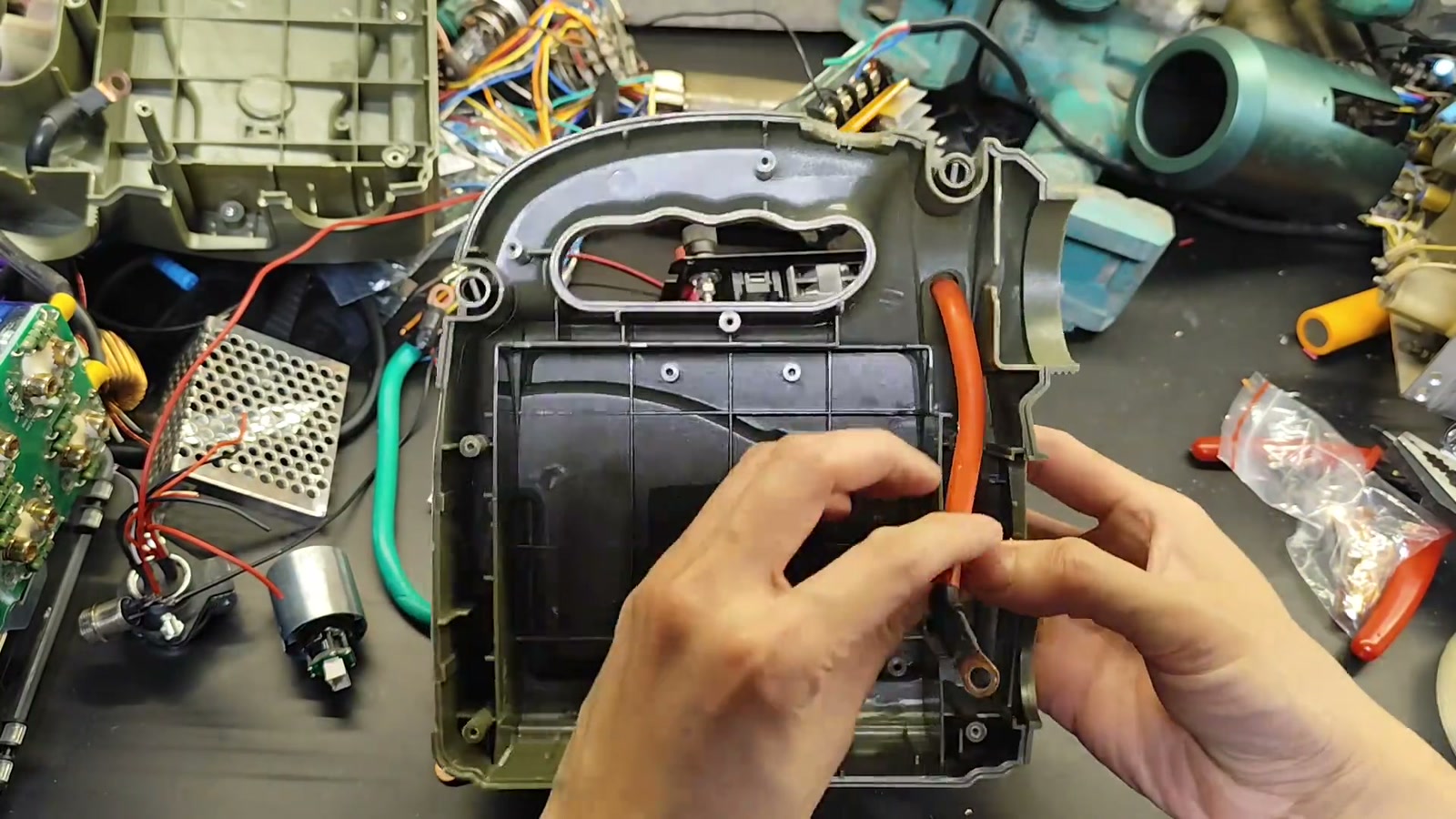
 Building a car jump starter from supercapacitors + lithium cells — the cells store energy, the supercapacitors deliver the big current; 21700 4000mAh cells in 2P4S, 2.7V 360F supercapacitors, two together should push past 100A instantaneous, CCA estimated 500+, should start a 2.4L car; final assembly and test nextProjectsDoomsday Lab