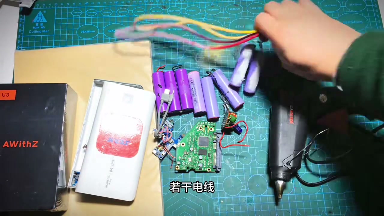
My first self-welded power bank, 20000mAh, and it lights up!
I was always too scared to touch spot welding — afraid something would blow up. The day my U3 Pro arrived I practiced on scrap nickel strip all afternoon, and today I did it for real.
Six salvaged cells, sorted by internal resistance. Tested it with a flashlight after welding: in 38 minutes it charged my phone full twice.
Grinning like I'd found money on the street. My wife says I'm acting like a kid. Yep.
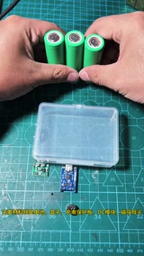
Maker Zhou Xiansheng’s step-by-step universal magnetic base guide (3325 likes): cells + box + charge/protection board + DC module + magnetic socket; a spare plastic box holds three 18650s, welder puts them in parallel ‘just rattle off the welds’, cut a hole to bring out the Type-C, solder charge board output → DC module input, protection board battery port and DC output, verify charging, glue it in, mark and drill the lid centred, push in the magnetic socket and solder + / −; pair it with whatever lamp you like
Lots of folks wanted the universal magnetic base guide, so this episode does it. Main materials: cells, a box, a charge/protection board, a DC module, a magnetic socket; the box can be wood, metal or even a brick, and the number of cells follows the box size; he picked a spare plastic box (comment: a floss box) that fits exactly three cells (comment: Samsung cells). First use the welder to put the cells in parallel — nothing fancy, just rattle off the welds, check they’re lined up and done; three fit in perfectly. Cut a hole to bring out the charge/protection board’s Type-C port; solder the charge board output leads, the DC module input leads, the protection board battery port and the DC module output leads; finally connect the cells and verify charging works; put the cells, protection board and DC module in the box and glue them down; mark and drill the lid as centred as possible for looks; push the magnetic socket into the hole and solder + and −; done, test the charging once more, perfect; how great is this universal magnetic base — pair it with whatever you want, use whichever lamp you want. 157 comments: why does the cheap 18650 charge/discharge module’s LED stay on (4); what does the DC module output; why is the 4056 double-layered / two input boards (creator: good eyes); Samsung cells are extravagant (a friend gave them); a 3D-printed base would be even better.
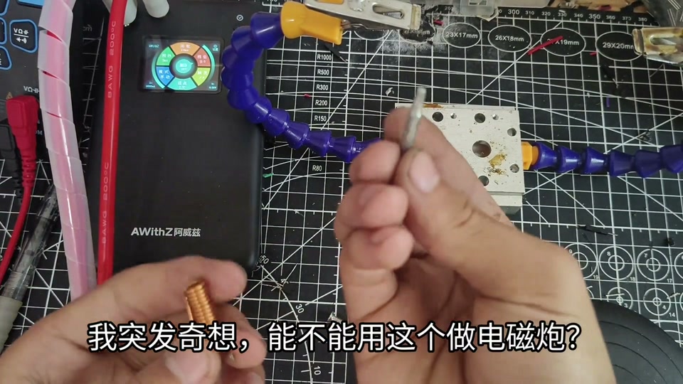
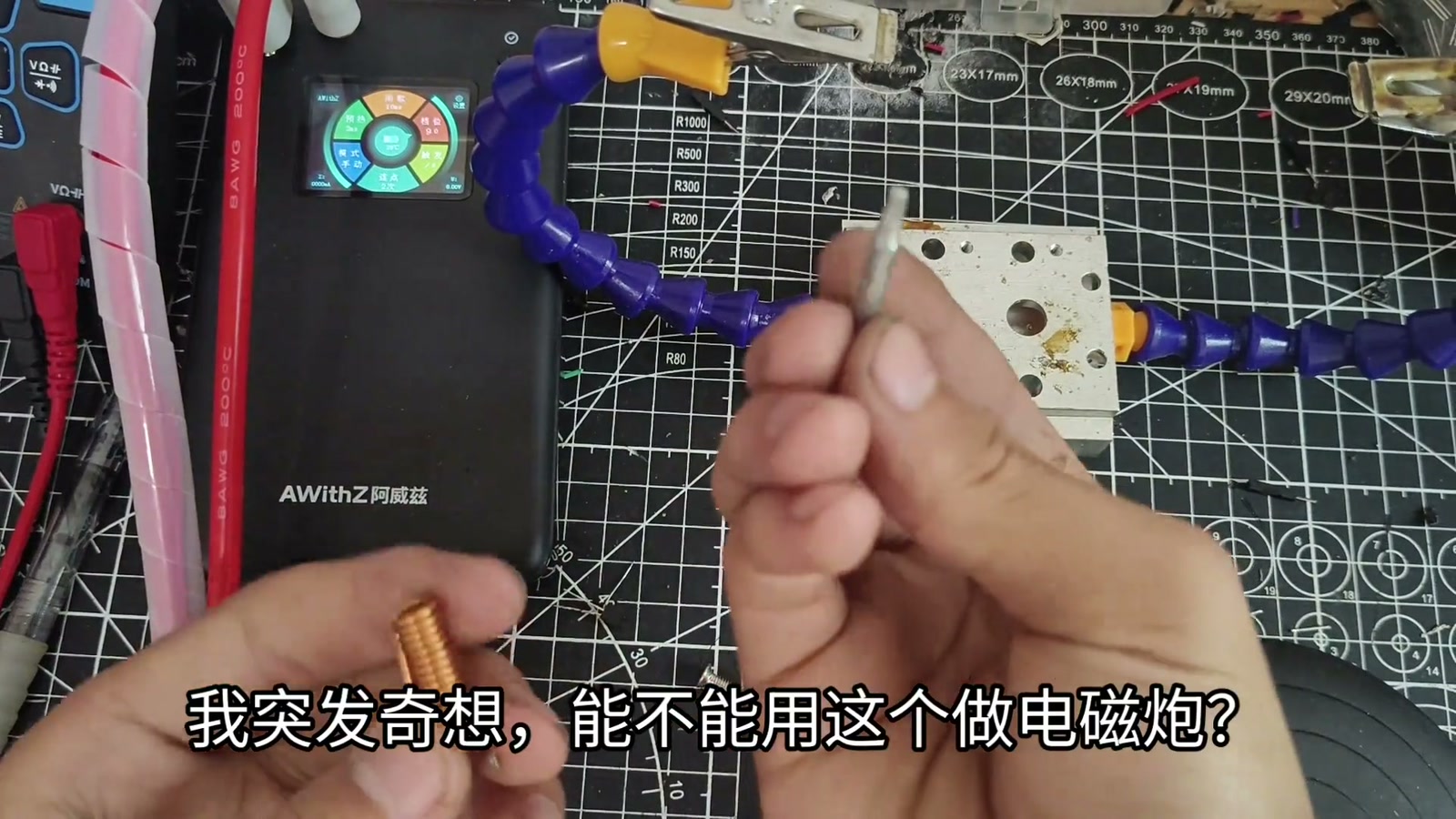
Zhizhi uses a high-current inductor + an AWithZ U3 (650A/4.2V) as the power source for an ‘ultra-low-voltage coilgun’: clamped in a vise, projectile pushed in, fired by the spot-weld trigger, decent power with visible recoil; the improved version has a thicker coil and only needs a press, no sparks, but a larger gap makes it less efficient; ‘the most powerful coilgun with the least copper’
A high-current inductor, and a sudden thought — could it make a coilgun; clamp it in a vise to test; push in the projectile; the resistance is tiny so it needs a high-current source, which brought the spot welder to mind — mine peaks at 650A with an output of only 4.2V, and if it works this is an ultra-low-voltage coilgun; try it straight away, decent power, you can see the recoil; the improved version has a thicker coil and only needs a press, no sparks, push in the projectile and try, efficiency seems a bit lower because the gap is a bit big; back to the original — truly the most powerful coilgun with the least copper; see you next episode. Comments: go study engineering, hand-build god (3); only 3.7V? the instantaneous high current makes the field that pushes it (creator: spot welders are all 1S or 2S, mine is 1S); a 310V one only manages this much; bubble-tea straw as the rail, thin is the point; could a supercapacitor be the power source.
DIY welder fail diary: a JX-D99 five-MOSFET welder board is a ‘toy’ without enough punch; adding MOSFETs, it blew after a dozen or so welds, a second one still wasn’t enough; finally switched to an AWithZ UF20B (1750A); welding 0.1 nickel strip gives bright, clean welds
The creator ‘teaches you welders’: first a JX-D99 welder board (a toy) + welding pens, hooked to a battery, five MOSFETs underneath; it felt underpowered so he added MOSFETs at the back, and after a dozen or so welds it blew; bought another and it still didn’t feel up to it; then switched to an AWithZ welder, model UF20B, 1750A, 5000W instantaneous (nameplate: 6.0V MAX, 1750A MAX, 10.5kW MAX, 100–240V, Shenzhen Juequi Technology); test-welded two pieces of 0.1-thick nickel strip — welds very good, bright and clean. Comments: ‘so the conclusion is you bought a welder for a few hundred bucks’, ‘you’re teaching us to buy a welder’, ‘talked into buying yet another one’; someone says Xiaoqiang’s can reach 2500+; someone claims a 5-MOSFET board with a 4S 120C battery at gear 75 can weld 0.1 nickel stacked on 0.5 copper (creator: no way).
Glue-stick mini fan tutorial: an empty 36g glue stick notched as the shell, two 16340s in series spot-welded with nickel strip on an AWithZ U3 Pro (auto mode), red and black wires welded on, potentiometer for speed + a switch, hot glue to hold it; only one cell can be charged at a time
A speed-adjustable mini fan made from an empty 36g Luofu glue stick. The old method melts through the screw post inside the stick; a heated knife cuts two opposite notches in the head of the stick; a heated wire opens a big hole in the cap, then flip it and cut two more notches. Take two 16340 Li-ion cells (UltraFire marked 3200mAh) and the U3 Pro-edition spot welder gifted by AWithZ official, power on and set auto mode (the body also doubles as a power bank); series: place one + up and one − up, lay the nickel strip on and spot weld — very solid; flip over, wrap a short piece of nickel strip around the ends of two wires and weld them to the other face of the cells, red + black −. Without a spot welder you can use a conductive plate and wrap the wires with electrical tape. Fan motor + switch, plus a low-value potentiometer for speed: bend one pin of the potentiometer to the motor’s other wire; red wire to the switch, black wire to the potentiometer’s middle pin; hot glue holds the wires; fold the side-by-side pack upright into the stick, drop in the motor, cap it; hot glue holds the potentiometer and switch, tape wraps the wires, fit the blades. Done, the potentiometer sets the speed; to charge you take it apart — only one cell at a time. Top-liked comment (45) warns ‘who taught you to spot weld like that? one cell going off because you didn’t press down and you’ll behave’ (creator liked it); suggestions: just wire it with a soldering iron, add a TP4056 charger, use a test tube for the shell, swap in a hobby-grade motor.
Turbojet gen 14: a car-turbocharger jet gets an afterburner, metal intake pipe + spot-welded thick steel tube; thrust 0.0009 → 0.0023 t, then the shaft seizes and it never self-sustains again
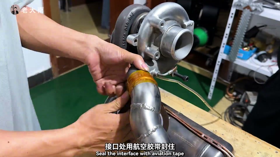
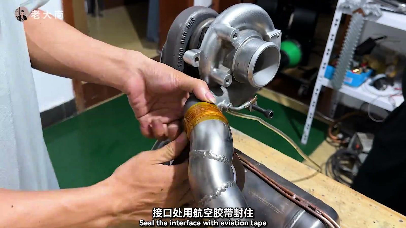
The previous generation, a turbojet built from a car turbocharger, reached self-sustain (0.0009 t of thrust, on LPG alone) and then blew its intake-side pressure hose after a dozen seconds. This time the intake is metal elbows joined and polished, sealed with aluminum tape; the bearing oil loop gets 120°C / 3.2MPa high-strength pressure hose with a pump circulating the oil. Because rich-oxygen combustion was wasting oxygen, an afterburner goes on the tail: a can cut up and steel tube sleeved over it — the tube was so thick he spent ¥3000+ on a higher-power welder before it would take a weld; a necked-down outlet adds thrust; a branch fuel line with several injection holes is tied into the main line so preheated fuel partly enters the afterburner for a second burn; a relief valve on the intake side guards against runaway rpm. A Guazi used-car ad is cut in midway. Test run: after self-sustain the shaft suddenly seizes, thrust hits 0.0023 t (more than double the last gen); opened up, the shaft spins freely again — suspected dust or over-speed, so a bigger steel-tube relief valve is added (screw sets the tension). The retry lacks pressure; he plugs it and patches leaks, but in the end it never self-sustains again — “give me my money back, I quit” — and looks ahead to gen 15.
12-minute unboxing and test of the AWithZ P30C capacitor spot welder: 3 × 1000F supercapacitors, 9V15A XT60 charging, usable after 5 minutes, 25 mm² pen cable, 999 gears; at gear 600 it welds 0.2×10 copper strip stacked on 0.15 nickel-plated steel strip to 21700s, external meter peaks 2070–2107A, strip tears apart without a weld letting go; gear 500 at 2052A also welds but 550–600 is recommended
An RC-model creator unboxes the more professional P30-series capacitor spot welder he chose for building 21700 power packs. Packaging: an intro card (32 patents worldwide), two accessory boxes and the main unit. Accessories: a 9V15A charger (charges the capacitors), a foot switch, an 18650 plastic welding jig, two spare pairs of welding pins, a very thick, soft pure-copper pen cable (later checked: 25 mm²), nickel strip (0.1 or 0.15), a file for dressing the tips, and the manual (battery icons, system settings, thermal protection — no charging above 60℃ or below -10℃, 2.4-inch color screen, about 180×131×80mm, auto power-off after 8 minutes idle, three ‘welding experience’ notes). The body is a boxy plastic shell but feels heavy; P30C model mark at bottom right; on the front a 2.4-inch color screen, power and control keys, two welding-pen ports and a trigger port; XT60 input at the rear. Nameplate: welding output voltage 9V (MAX), output current 2430A (MAX), max output power 21.8kW, input 9V/15A. Red warning: the two tips of a P-series pen may only touch the same terminal plate of a cell — never touch the two plates separately, or it shorts and catches fire. Main screen on power-up: welding mode (manual / auto), preheat time, interval time, welding gear, trigger time, repeat count; OK means ready to weld, a slash means low battery; internal temperature shows 27℃; system settings: language, repeat interval, welding sound, screen brightness, screen rotation, auto power-off, factory reset; plus three ‘welding experience’ notes (results depend on pen pressure, material thickness and stacking order) — helpful for beginners. Inside are three 1000F supercapacitors; from completely flat, 5 minutes of charging is enough to weld. The pins are imported alumina copper. Test: straight to 0.2×10mm copper strip stacked on 0.15 nickel-plated steel strip (the nickel layer adds resistance so the copper can be welded to the cell), starting at gear 600 (max 999) with an external welding-current meter connected; he recommends keeping the charger plugged in while welding to top up at any time. Gear 600: four welds, peak 2070A, RMS 1574A; pulling tears the strip apart, fully welded. Down to gear 500: 2052A, both welds hold too (one torn through, one shows copper flow), but to be safe 550–600; back to 600 for 3 more shots, 6 welds, all tear apart with no weld letting go, current 2107A — the rated max is 2400-odd amps and gear 600 is already enough. Conclusion: 0.1/0.15/0.2 and even 0.3 nickel-plated steel strip, and 0.2 copper stacked on 0.1/0.15 nickel, are no problem at all — fully up to building 21700 power packs; long-term performance to be seen once he builds packs with it. Comments: ‘only 2000A at this price’, doubts that 2000A can weld 0.2 copper on 0.15, someone’s ¥336 home-built welder does the same but with tearing, and someone says 0.15+0.15 tears at gear 270 after switching to a one-piece pen.
16 × 15Ah LiFePO4 cells in 16S1P for a 48V e-bike battery, the full 30 minutes: nickel strip stacked on copper, a self-built welder that overheated and stopped work, a 60V/20A Bluetooth BMS, 16.5A measured on the bike
The creator builds a 48V LiFePO4 battery for an e-bike that has run on lead-acid for three or four years: 16 × 3.2V/15Ah cells all in series come to exactly 48V. To carry more current he stacks copper strip on nickel strip, and first tries two machines: the self-built welder welds 0.12 nickel-plated steel strip + 0.1 copper, the handheld welder welds 0.12 + 0.05 copper, both solid, and he mainly uses the self-built one (it can weld thicker copper). All 16 cells read 3.297V with 1.7–2mΩ internal resistance, so he builds without balancing. Triple holders are assembled (one holder with four extra corners wouldn’t fit and got trimmed), insulating paper applied, nickel and copper strip 15mm wide, the nickel strip’s sharp corners trimmed on the positive side; the jump starter that powers the welder is put on charge. During welding the self-built machine (with added capacitors, shortened leads and swapped MOSFETs), its thermal pad, the jump starter and the cells all get too hot to touch, so he keeps stopping to cool them with a fan; the jump starter won’t charge at 5V2A, so he pulls the 60V/20A Bluetooth BMS (switchable NMC / LiFePO4) from a previous 21700 pack. After several ‘won’t weld’ episodes he finds he had stacked two layers of copper by mistake; later he adds nickel strip to compensate. Main + to main − reads 52.7V, total internal resistance 32mΩ. 704 silicone to fix, mesh double-sided tape for the ribbon, sense leads soldered group by group and tinned (‘nearly had an accident’), lead order checked, 3 hours 40 minutes in total; the Bluetooth app gets LiFePO4 settings: over-voltage 3.65, under-voltage 2.3, balancing from 3.5; insulating board, main positive and temperature probe go in, insulating paper on, and heat-shrink film can be done with a hair dryer (keep it out of the sun). Lead-acid measures 89mΩ for comparison; the battery bay is bigger than expected (would take 48V30Ah); adhesive-lined heat-shrink for waterproofing; on the bike the app shows 53.0V, -16.5A, 14.8Ah, 0.038V delta, 0.9kW. LiFePO4 isn’t ideal for northern winters, but it’s cheap, safe and fades less than lead-acid. The top comment says the video is too long.
A ‘TNT’ C4-style power bank from a dead power bank’s charge/discharge board + 18650s + a kraft-paper tube, plus an unboxing of the AWithZ portable welder (setting around 4.3, mid-range)
The creator (a designer-toy channel) wanted a C4 explosive-pack power bank with a timer look. Materials: a dead power bank (for its charge/discharge board), 18650 cells, a few circuit boards as decoration, a glue gun, wire, kraft paper. Along the way he unboxes the AWithZ portable welder: about the size of a 10000mAh power bank, doubles as a power bank itself, comes with a welding pen (very thick copper tip), nickel strip, manual, charging cable and sandpaper; in settings he switches to Chinese, turns on the welding sound, sets auto trigger 0.5s / 1.0s; power at eight-point-something throws too many sparks and punches through the cell, too little won’t hold, so mid-range around 4.3 is right. Kraft paper is misted with a little water to soften it, then rolled into cell tubes; several groups of cells go in parallel (red is positive — remember parallel, not series), get stuffed into the paper tube and fixed with hot glue, the charge/discharge panel and decorative boards are glued on, and the wires are spot-welded instead of soldered (no preheat, welds wherever you touch, with vibration feedback); powered up it shows 34% charge; a coiled cable and black tape finish the weathered look. Warning: don’t take it into crowds or onto public transport.
Ran into a problem? Have an idea for improvement? Tell us. We read every piece of feedback carefully. Valid feedback earns points, redeemable for accessories / coupons.
Thanks for your feedback!
We'll review it within 1–5 business days. If you left an email, valid feedback earns points redeemable for accessories / coupons. If we need to follow up, we'll contact you at the email you left.
WeldWorld is an open platform for user sharing; content does not represent official advice.
Improper battery handling can cause fire, explosion, chemical burns and serious injury. Read the full AWithZ Safety & Usage Guidelines before any lithium battery assembly, spot welding or testing, and before using the community.
Community content is personal experience, not verified by AWithZ; where it conflicts with official documents, the official documents prevail.
Never apply someone else's settings directly; always start at a low level and test on scrap.
Before copying any procedure, go through the self-check list in Part 3 of the guidelines.
 LV3
LV3
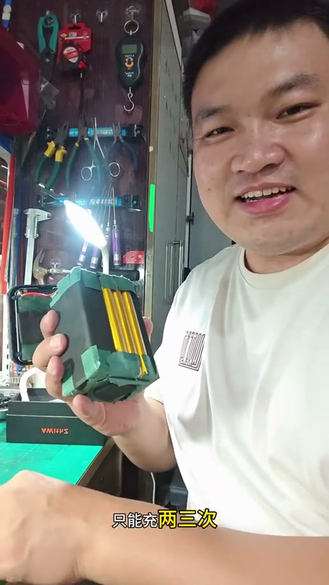


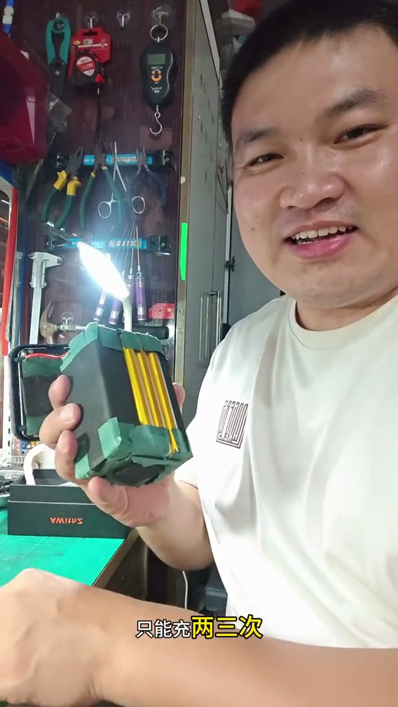


 Anyone else burned by a power bank? I went for a battery spot welder — power-bank freedom! Totally hookedProjectsChubby Li~

 LV2
LV2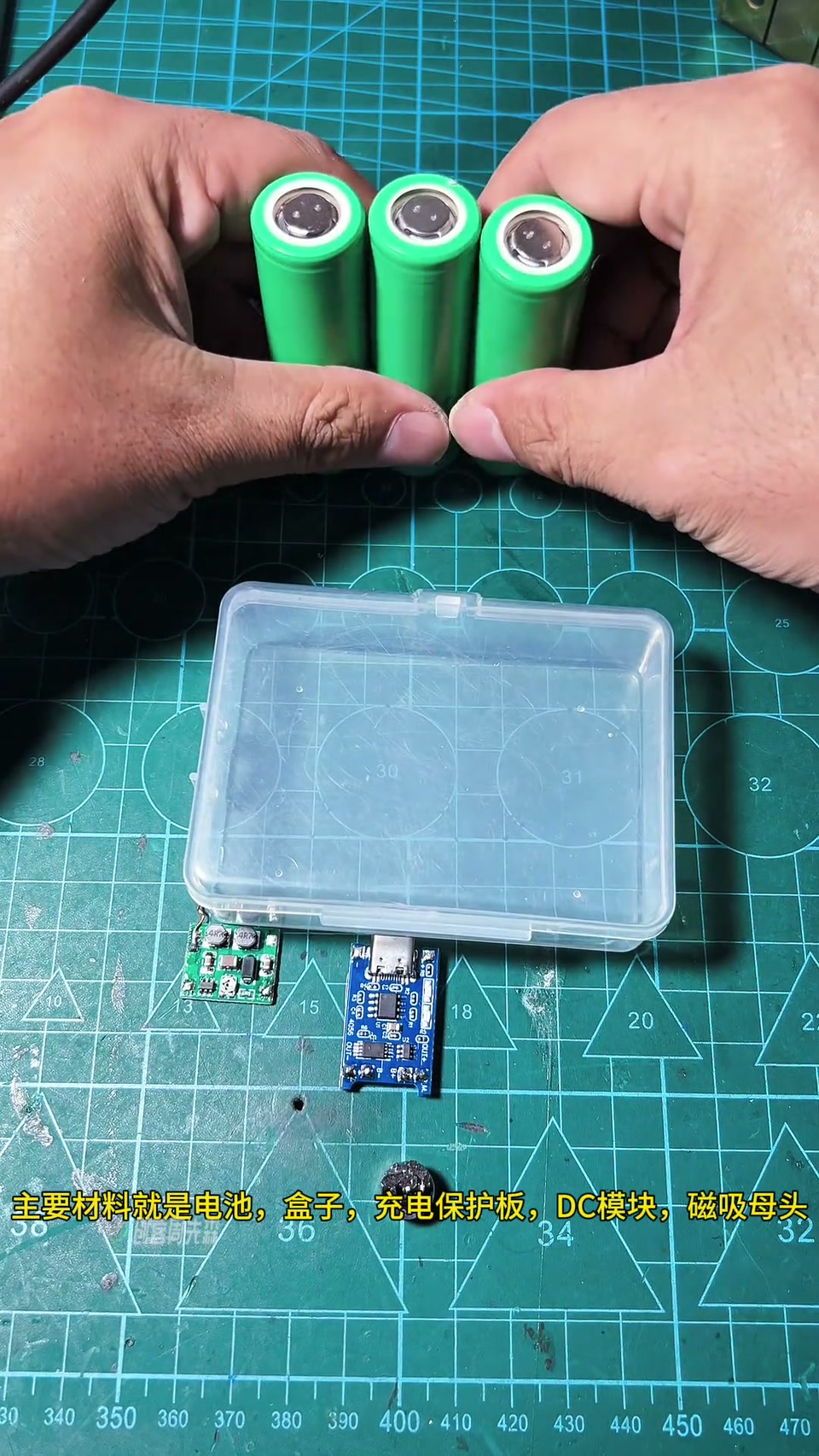





 LV1
LV1
 LV2
LV2