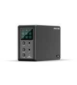
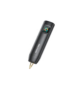
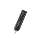
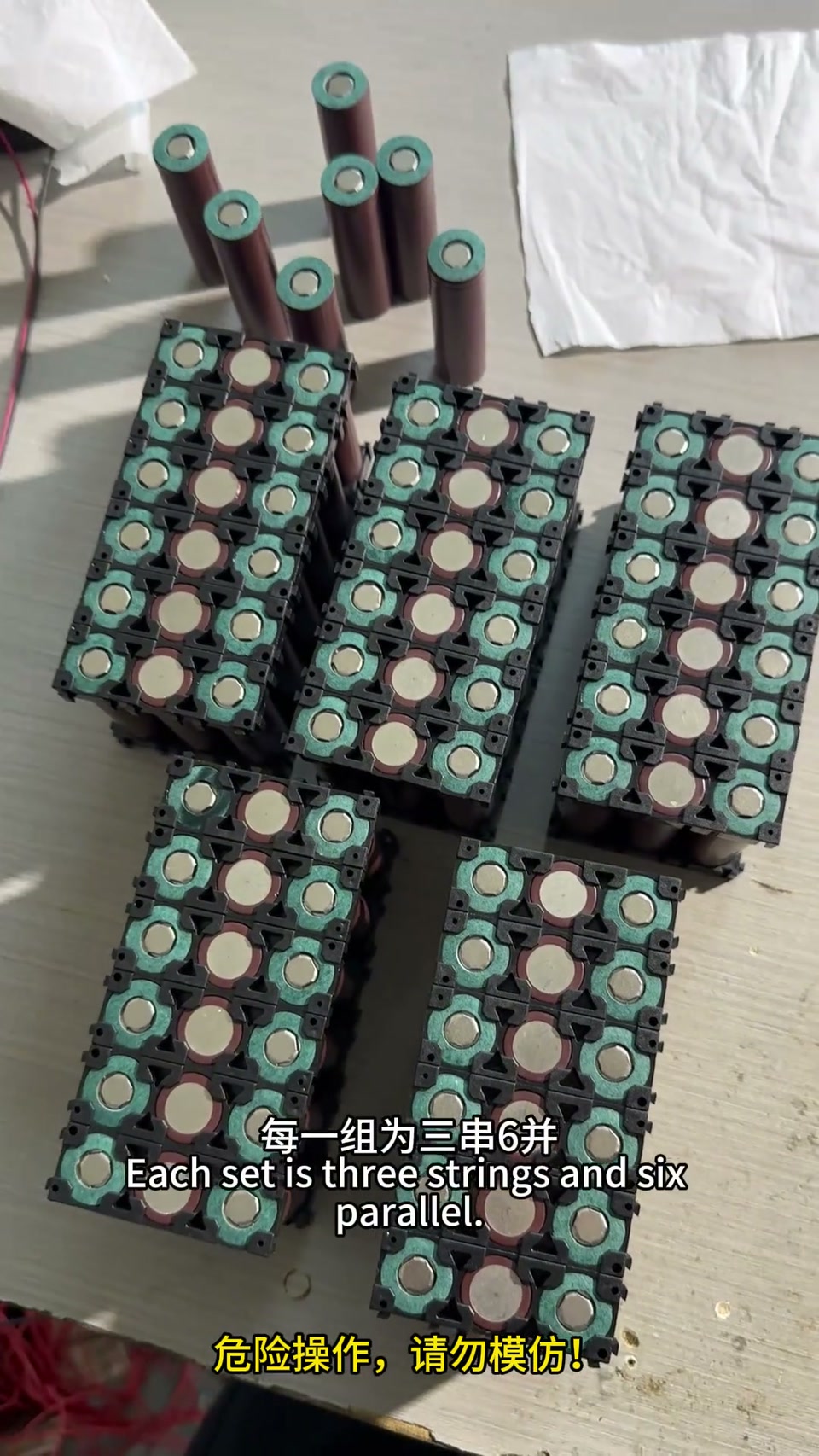
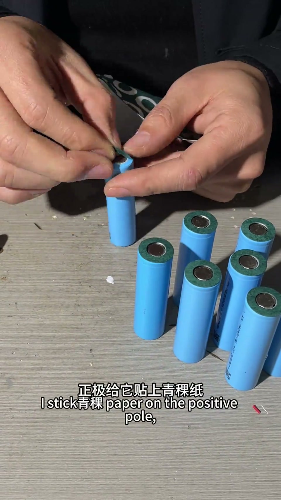
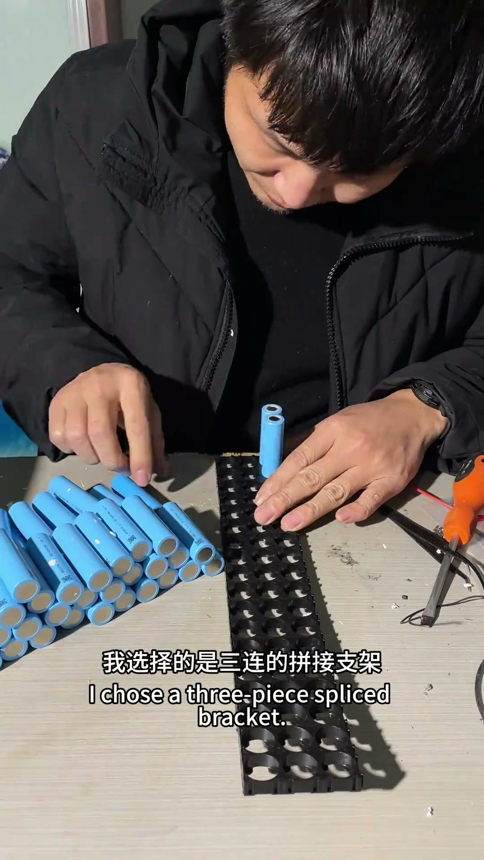
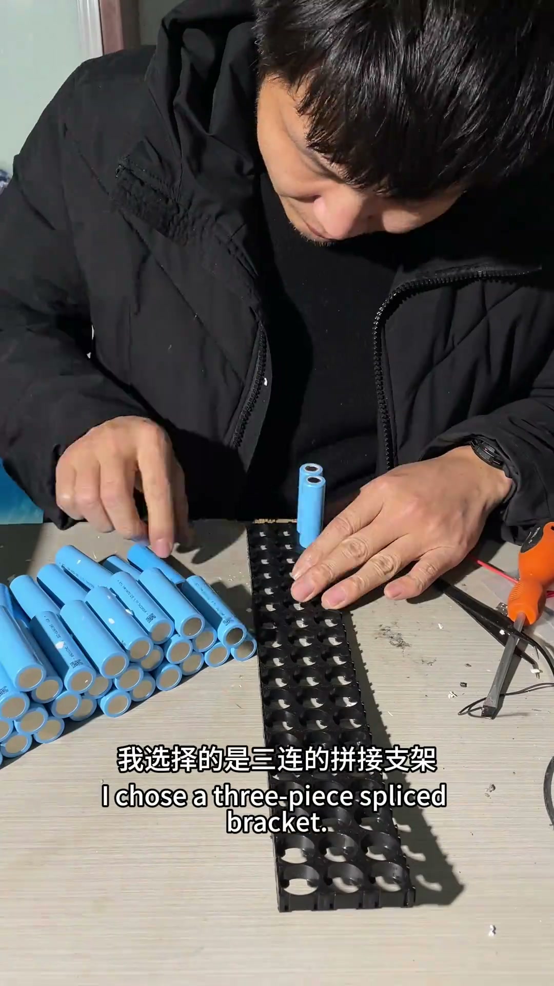
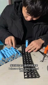
Built a flashlight that lights up half the street for under 20 yuan
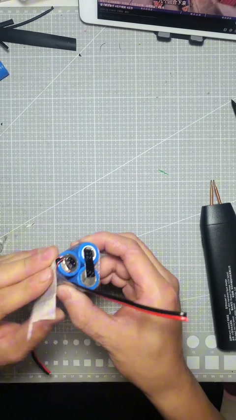
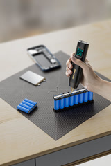
Three 18650s plus an e-bike headlight, with a water pipe for the housing. Welded the nickel strip with the H1 — tiny little thing, handles 0.12 strip with zero effort.
Switched it on outside at night and the neighbors thought someone had left their car headlights on. Hahahaha.
Pic 2 shows the internal wiring, for anyone who wants to copy my homework.
Lefeng ‘blowing it up, bro’ round three: the P60F pen is longer than the UF20B’s and not fully enclosed (has a gap), so while welding the main negative it touched a positive / another strip — bang, two shorts, blackened pen, cable ripped off; nickel strip edges cut his hand; the 50A copper lugs for main +/− were too thick, so switched to screw terminals with heat-shrink; the positive red lead must never be swapped; remedy: high-temperature glue + cutting paper + fireproof board over the pen gap, main +/− sealed with 704 silicone, fiber tape, then solder the sense harness; comments: sleeve the pen in nylon braid / polyimide film, same pen blew through a 50 mm² welding cable
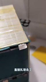
Straight short, ‘blew it up, bro’, cotton swab from the bag to wipe his hand — just got cut by the nickel strip again, the welding pen touched the strip and blew twice; the corner of the strip went in and it ‘burst like tomato juice’, this build really wrecks your hands. The 50A copper lug connected and a dab of solder on it; meant to spot-weld it onto the copper plate but found the lug too thick, so back to the old way, screw it, heat-shrink over it, onto the copper plate, then spot-weld to the main positive and negative; when soldering the leads the positive must go to the red positive, get it wrong and it blows up again. Nearly blew it up again just now: welding the main negative, this pen isn’t fully wrapped, it has a gap, the gap touched a positive, bang, the cable was ripped straight off, terrifying, the cable feels unsafely designed — not fully enclosed, and yes enclosing it hurts cooling, but I keep touching other things, clip another strip and it blows; same recipe as before: high-temperature glue, then cutting paper, then a layer of fireproof board on top, this corner is the blackened spot; the short blew right at the pen; this time the main +/− get sealed with 704 silicone first, then a few turns of fiber tape and the sense harness can be soldered. Comments (116): sleeve the pen in nylon braided mesh (noted); my pen is identical and it blew straight through the 50 mm² welding cable, only a few strands left (that bad?); wrap it in polyimide film; no BMS? not on LiFePO4?; solder the main +/− straight onto the copper plate (I prefer screws); safety first (scared stiff); running deliveries in Changsha.
Lefeng puts 0.2 copper + 0.15 nickel-plated straight onto a Jiashikai negative with the P60F: gear 400 sticks the pins and the nickel strip is pierced without the copper bonding; thinner nickel at gear 450 still won’t take, “these holes crack me up”; preheat adjusted, gear 600; gear 700 “burnt black, way too strong” but finally can’t be pulled off, cuts his hand, the 0.2 copper tears into a hole before it counts as welded — “I’m telling you, don’t try it, the current is too high”; comments: weld the copper first then the nickel / use thick 3mm round-tip pins / your skills are questionable
I’m telling you not to try this: this time 0.2 copper sheet plus 0.15 nickel-plated steel strip goes straight on, no nickel base layer; a test weld first, the cell wasn’t sanded, it just has a few old holes from before; the welder is an AWithZ P60F, gear 400, preheat 0.1, interval 1ms; before he even welds, someone says it won’t hold; the current is fierce, you can’t go in square-on or it burns right through the sheet, keep the pens as flat as possible; the pins stuck; it didn’t bond but the nickel strip was pierced clean through, the technique must be wrong, 0.2 copper and nickel both burned with holes and still no bond, or maybe I don’t know how to run the machine; an internal-resistance meter (HRM-10) reads the cell at 3.32V; swap to thinner nickel strip and try, still 0.2 copper strip, gear 450, looks like it might take this time? no, it won’t, forget it, these punched holes crack me up; back to the nickel-plated steel strip, I refuse to believe it; adjusted the preheat, gear 600, whether it’ll punch through the cell I don’t know, getting a bit annoyed after it wouldn’t hold; gear 700: this looks burnt black, too big, too strong; truly can’t be pulled off, cut my hand; now it really won’t come off, the copper stuck to the top, the 0.2 copper strip torn right into a hole; if that’s not enough I’ll add another 100 gears, that’ll definitely do it; so that’s why I tell you not to try 0.2 copper lightly, it just blew two holes, and at gear 700 the current is still too high. 308 comments: if this welder can weld 0.2 copper, every spot-welder seller online can shut down (2); my ¥100-odd unit does 0.1 stacked on 0.1 copper no sweat (2); your skills are questionable; bought a UF20B after your video and it can’t weld 0.1 + 0.1; 0.2 copper + 0.15 nickel-plated won’t take, add 0.1 nickel-plated and you still need flux paste; pins too thin, use 3mm round tips; 700 works, thick pins are best; weld the copper first then the nickel (are you serious?); test the Xiaoqiang; a four-capacitor rig welds it instantly.
Xiangzi Workshop (dealer), 57 seconds: tested the UF20B on livestream welding 0.15 stacked on 0.15 copper strip directly, very strong; all-aluminum shell looks great, big color screen, the pen has a trigger switch (press down, then click), auto / manual selectable, nice welds; go see his buddy’s shop window; a comment warns you need the 15 mm² pen cable, 8 mm² won’t weld copper
Tested the UF20B’s welding ability on livestream: went straight to 0.15 stacked on 0.15 copper strip, very strong (on camera he welds a 0.15 nickel + copper stack onto a cell and shows the welds). This all-aluminum shell looks great overall, with a big color screen; the welding pen has a trigger switch, press it down and click the switch for an easy weld; auto / manual selectable; the welds all look very nice; if you need one, go to his buddy (Xiao Wang) for details, worth recommending. Comments: are the pen cables you send the same ones (I sent two kinds); why is my cable different and running so hot; you must use the 15 mm² pen cable, 8 mm² won’t weld copper.
Don't throw away a dead power-drill battery! Fix it yourself with this 'portable wonder' and save more than half the cost! Small footprint, plenty of power. H1 handheld dual-pulse spot welder! #BatteryRepair #diy #Handmade #WeldingEquipment #PowerTools
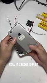
iPhone 6 modded to 20,000mAh: 4 × L700 (5000mAh) in 4P, nickel strip joined with an AWithZ spot welder, hot-glued to the back of the phone, a 45℃ thermal switch auto-starts a cooling fan
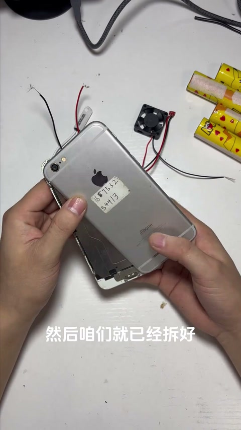
Turning a years-old iPhone 6 battery that only lasts half an hour into an external 20,000mAh pack. Teardown: open the cover plate, remove the battery connector bracket, pry the battery out with a spudger; drill a small M3 hole in the case, then widen and deburr it so it won’t cut the wire, and route the iPhone 6’s power flex through the hole to the back. First test with 1 L700 taped to + and −: no light the first time because the flex wasn’t clipped in tight; press it down and ‘3, 2, 1, on’, swiping works. Then the big battery: 4 × L700 (5000mAh each) in 4P = 20,000mAh; out comes the AWithZ spot welder, nickel strip joins the positives and likewise the negatives, with fish paper for insulation. The hot-glue gun first dabs the power flex so it can’t come loose, then the back of the phone is covered in hot glue to stick the battery on, both sides filled so it won’t wobble. A soldering iron tins the nickel strip and the wire ends, then solders + and −; it boots to the home screen, Wi-Fi works. Finally a 45℃ thermal switch (actual part marked KSD9700 50℃ 250V10A) is wired to a cooling fan, hot glue holds the switch and fan together, the switch’s + and − are soldered to the battery: once the case goes over 45℃ the fan starts by itself, no physical button. Camera and swiping work — done. Top-liked correction in the comments: charging without a BMS is very dangerous, a 21700 is 4.2V full while an iPhone battery is 4.45V; others worry the big battery will fry the logic board, and ask how to read the charge percentage.
Hand-built portable digitally controlled adjustable supply: 3S4P 18650 + 3S40A BMS, boosted to 36V then through a digital buck module with coulomb counter, 0–33V adjustable with adjustable current
The creator wanted an adjustable supply that works without mains — for the price of one you can hand-build four. The core is an adjustable buck module with a coulomb-counter display; power comes from 12 × 18650 in 3S4P (12.6V) with a 3S 40A BMS. A plastic box is cut for the quick charge port, a square hole for the coulomb-counter display, round holes on both sides, vent holes and a fan slot, a battery gauge and a master switch. The charge input feeds a CC/CV buck-boost module with charge management, output set to 12.7–12.8V; two 40℃ normally-open thermostat switches in parallel control the fan (one stuck on the boost module heatsink), with the fan and gauge negatives on the boost module input. Battery 12.6V goes through the master switch into the boost module set to 36V max, then into the digitally controlled regulator module with thyristor; output leads with clips on the output terminals, the coulomb counter’s ribbon cable into the core board. Power on — charging works, the coulomb counter lights red, a multimeter on the output clips shows the knob sets voltage precisely, up to 33V; it can charge while in use, set voltage and current precisely for load tests, and work as a universal charger for all kinds of batteries.
Electric grass trimmer from scrap: galvanized pipe + steel plate + belt-driven 775 motor, powered by a 3S5P 18650 pack through a boost module at 33V
One end of a two-metre galvanized pipe is cut at an angle and a steel plate is welded on tilted about 45° (like a small hoe); a handle is welded on wherever it feels right. Four holes in the plate take two bearings (as close to one straight line as possible), a shaft goes in and the excess is cut off, then an adapter, clamp plate and small pulley are fitted. A bracket for the 775 motor is welded on; once cool, the 775 motor and belt go on, and a powered test shows it runs smoothly. For power, 18650 cells make a 3S5P pack with a balancing BMS, fitted into a box with input / output / gauge / switch holes cut in it; the charge input gets a CV/CC buck-boost module with charge management set to about 12.8V; the battery positive runs through the switch into a boost module set to 33V feeding the 24V 775 motor — more torque and more speed. The box is fixed to the tail of the pole, the output lead connected, a shoulder strap tied on and trimmer line fitted (soft wire for now). A test cut at the front door works well — lighter and quieter than a petrol trimmer.
90 × 18650 in five 3S6P groups paralleled into one big 12V battery; a storage box becomes a solar outdoor power station: 1kW inverter + 90W fast charge + 22W wireless charging + thermostat-controlled fans
The creator buys 100 × 18650 cells at ¥2.5 each (2000mAh, 5C discharge), tests the internal resistance of every one (3 read high and are rejected), picks 90, puts a fish-paper ring on each positive end, loads them into holders and builds five 3S6P packs. When spot welding, a copper strip is laid under the nickel strip to raise current capacity; each group is wrapped in fish paper, gets its balance lead and main + / − brought out (thicker wire for current), gets its own BMS, then is wrapped in fish paper again and bound with fiber tape. The storage box (with carry handle) gets a battery fuel gauge top-left and a voltmeter top-right, a front cutout for the 90W charging module, one cooling fan on each side (one intake, one exhaust), an aviation connector with waterproof cap on the back as the charge port, and a 22W wireless charging module; the five packs sit in the bottom of the box, the output leads are twisted into one bundle (one thick, three thin), tinned with a flame and covered in heat-shrink. Charging goes through a constant-voltage / constant-current buck-boost module, DC input up to 30V (a solar panel under 30V can be connected), output set to about 12.7V with a multimeter; two thermostat switches, one stuck to the buck-boost module heatsink and one to the inverter housing, control the fans; the thick leads get crimped terminals reinforced with molten solder to the 1kW inverter, and two 220V sockets are paralleled onto the inverter output. A ‘dangerous operation, do not imitate’ warning stays on screen for the whole video.
Two 6.5-inch full-range car speakers + a Bluetooth amp board + a 15 × 18650 3S5P 12V power box: a home stereo for under ¥100
Two full-range (bass/treble) car speakers go into two 6.5-inch pre-cut speaker boxes: the positive and negative leads pass through the wiring hole, and the speakers are screwed in. The amp is an XY-T30L module with Bluetooth and bass/treble control; plug in the left and right channels, the speaker terminals are screwless, and it runs on 12 or 24V. To keep things simple for the older folks, he builds a dedicated power supply: 15 × 18650 cells with fish paper on the positive ends in a dedicated holder, 3S5P for 12V, fish paper around the outside against knocks, then spot-welded. A balancing BMS is a must; the multimeter reads 10.8V at input/output (not fully charged, normal), 3.6V for one group and 7.2V for two. The common-port input/output leads are connected and protected with fish paper + fibre tape. The box is drilled for a switch, battery gauge, charge input and power output; charging uses a 5–30V-input constant-voltage/constant-current buck-boost module set to about 12.6/12.7V, insulated with heat-shrink. Battery output and charge input both go to the switch input; all negative leads are twisted together, tinned and heat-shrunk. On power-up the gauge shows 2 bars; the lid goes on with screws, the phone connects over Bluetooth and plays, and the creator claims ¥1000-class sound quality. Commenters think the box size doesn’t match and a digital amp is just loud.
A ¥20–30 DIY fast-charge power bank with an honest rating: 8 × 2000mAh 18650 all in parallel for 16000mAh + a ¥10-ish boost fast-charge module + a PVC-sheet case
The heart of it is a power-bank boost module with a digital charge readout and fast-charge protocol support (about ¥10), paired with 8 × 18650 (¥2–3 each). Test the cells’ internal resistance, stick fish paper on the positive ends, load them into a single-row holder and wire everything in parallel (the module is a boost type, so it only needs 3.7–4.2V); 8 × 2000mAh = 16000mAh. Wrap in fish paper, spot-weld, insulate the positive and negative ends again with fish paper, measure 3.6–3.7V, solder leads onto the positive and negative pads and wrap the joints with filament tape. Two wires go to the module; press the switch and it shows the charge level. The case is hand-cut from PVC sheet (a 3D printer would look nicer), openings cut with a home-made fret saw and a small electric saw, glued with strong adhesive, with cut-outs for the display, the USB / Type-C ports and a small button. The Type-C port does input and output; with a powerful enough charger it goes into fast charge (green lightning icon), the USB port also fast-charges, and it will keep a phone going for two or three days.
¥1 junkyard speaker turned into a wireless Bluetooth speaker: the original amp board won’t amplify the Bluetooth signal, so the Bluetooth board drives the speaker directly + 6 × 18650 cells
An old powered speaker picked up at the scrapyard (under ¥1); fuse good, a hum on power-up, transformer output normal. The plan was to feed the Bluetooth module’s audio output into the original board’s audio input, but it didn’t amplify; switched to driving the speaker straight from the Bluetooth board, which works. So everything original except the driver comes out and it becomes rechargeable — 6 × 18650 spot-welded into a pack with a 3S60A balancing BMS, fish paper insulation and fibre tape; a diode and a CC/CV buck module on the charge side; a fast-charge port, charge-level display module and switch in the case; wired up, powers on, back in the case, phone pairs and plays, ‘sound quality is decent for its size’. The top comment points out that without audio amplification the result is only so-so.
54 × 18650 cells in 3S18P for a 12.6V 36Ah outdoor power box: 220V inverter + wireless charging + USB + solar charging + thermostat-controlled fans
The creator takes 54 × 5C-discharge 18650 cells (about 16mΩ internal resistance; IR and voltage tested first, any 20mΩ cells swapped out) and loads them into snap-together triple holders for a 3S18P pack, 12.6V full and 36000mAh; fish paper on the positive ends against shorts. Spot-welded with double-layer nickel strip on the high-power AWithZ welder; midway the two pens touched and blew through the strip and one cell, so that cell was pulled and replaced. A 120A balancing BMS goes on, the main + and − are brought out with copper wire wrapped around and flooded with solder from the iron, then wrapped in fish paper and fibre tape. The box gets a bidirectional smart meter (with shunt), a 220V socket, power switch, 90W USB fast-charge module, wireless charging module, a CC/CV buck-boost charging module with 5–30V input (output set to 12.6/12.8V, about 5A, diode in series), a 600W / 1200W-peak pure sine wave inverter, two fans + three 40℃ thermostat switches in parallel (one each on the inverter heatsink, the BMS and the buck-boost module), and finally a carry handle. It can cook rice and run a hot pot, drive power tools, jump-charge an e-bike, and charge straight from any 5–30V charger or solar panel.
Ran into a problem? Have an idea for improvement? Tell us. We read every piece of feedback carefully. Valid feedback earns points, redeemable for accessories / coupons.
Thanks for your feedback!
We'll review it within 1–5 business days. If you left an email, valid feedback earns points redeemable for accessories / coupons. If we need to follow up, we'll contact you at the email you left.
WeldWorld is an open platform for user sharing; content does not represent official advice.
Improper battery handling can cause fire, explosion, chemical burns and serious injury. Read the full AWithZ Safety & Usage Guidelines before any lithium battery assembly, spot welding or testing, and before using the community.
Community content is personal experience, not verified by AWithZ; where it conflicts with official documents, the official documents prevail.
Never apply someone else's settings directly; always start at a low level and test on scrap.
Before copying any procedure, go through the self-check list in Part 3 of the guidelines.


 DIY high-power flashlight tutorial: three 18650 cells and an e-bike headlight for under ¥20ProjectsGoodnight


 LV5
LV5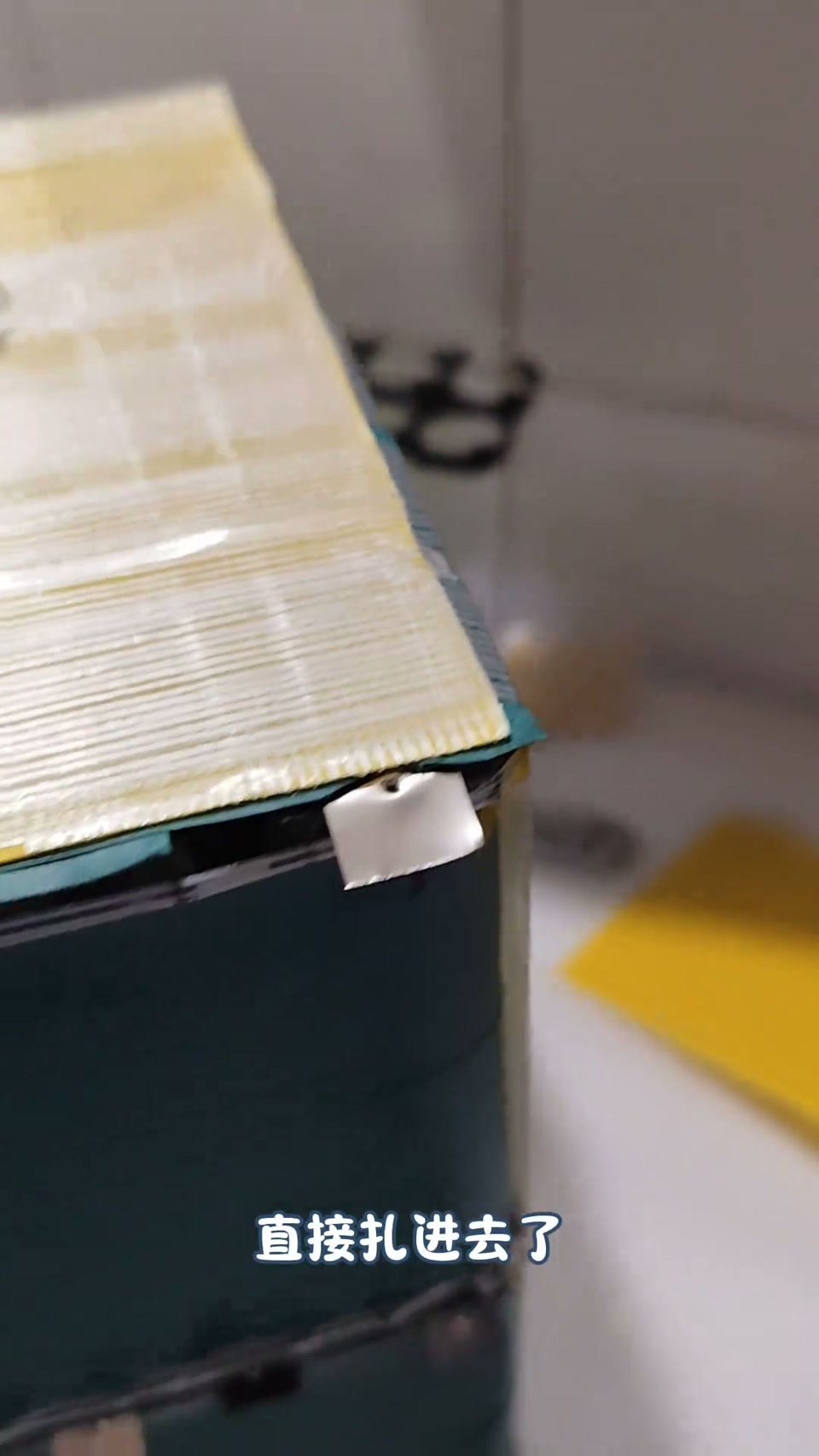



 LV5
LV5
 LV1
LV1